- Joined
- Sep 1, 2023
- Messages
- 68
I have read the threads about VFDs conversions on this forum, and on the practical machinist site, and I was surprised that the need to step up the voltage (from 240v to 550v or 600v) is seldom discussed, my understanding is that some 3 phase motors are designed for 240v, and some motors designed for higher voltage are fine with 240v comming out of the VFD.
My home hobbyist shop only has 1 phase current, 240v and 120v.
My recently aquired HLV (like all HLVs), has 2 windings/circuits for the motor.
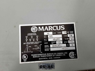
The specs for the motor are:
550 volts
circuit 1: 1 hp at 1710 rpm
circuit 2: 0.5 hp at 530 rpm
I was thinking of wiring a VFD to the 1st circuit (1hp at 1710 rpm), see how it goes, and If I find that I don't have enough power at low RPM, then think about adding a second VFD for the second circuit, or something more sophisticated like a "shut everything off and rewire to the vfd to the second circuit" mechanism.
Will this work ?
SHould I used the 2n circuit (0.5 hp) instead ?
Any recommendations on a particular VFD model, features, etc ?
For the coolant pump and power feed motor, I will deal with it later.
My home hobbyist shop only has 1 phase current, 240v and 120v.
My recently aquired HLV (like all HLVs), has 2 windings/circuits for the motor.
The specs for the motor are:
550 volts
circuit 1: 1 hp at 1710 rpm
circuit 2: 0.5 hp at 530 rpm
I was thinking of wiring a VFD to the 1st circuit (1hp at 1710 rpm), see how it goes, and If I find that I don't have enough power at low RPM, then think about adding a second VFD for the second circuit, or something more sophisticated like a "shut everything off and rewire to the vfd to the second circuit" mechanism.
Will this work ?
SHould I used the 2n circuit (0.5 hp) instead ?
Any recommendations on a particular VFD model, features, etc ?
For the coolant pump and power feed motor, I will deal with it later.