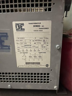
One can usually run transformers in reverse. It has more to do with the voltage and current break down ratings of the wire insulation than the wire itself. Of course the photo you show when hooked up in reverse would indicate that the input delta and Y configurations are also reverse. The diagram indicates that the primary is H's (delta, 600 VAC) and the secondary connections, X's, are Y (208 VAC) configured. But you would be reversing these. Input is now Y and output is then delta.
I assume what you are talking about here is to connect a VFD to the single phase 220VAC from your home. You then set up the VFD out to 220VAC three phase output into the 208VAC Y configured Transformer windings. The motor would then be connected to the Delta outputs of the transformer.
I would not do this myself as it introduces a bunch of other issues and you do not know how the motor, transformer, VFD are going to react to them ... and of course not all VFDs or motors are made the same. The in concept transformers similar, but in practice they differ. I once had to spec a custom transformer for an inhouse power supply I was designing and I can tell you I purchased several and they did not all behave the same..... At no load they were pretty similar, but with load their output wave forms were considerably different both in peak voltages and currents and in distortion. In concept the VFD outputs a the frequency you tell it to. It also outputs a pulse width modulated voltage not a sine wave. The motor inductance smooths this waveform out, but the VFD its suppose to be tuned to the motor behavior. All of which is impossible to optimize for all possible frequencies. Now you toss in a transformer and you decide to run the motor/VFD at lower or higher frequency than 60cps and the transformer does not work right.
One of the nice properties of the VFD is that you can vary the frequency output to alter the motor speed. It is not clear how much you might be giving up here due to the behavior of an unknown transformer.
If you had all these parts, without having to spend money, then you could just try them out. But if you are going to lay out money it would be a shame to find out that they did not work right when put together.
If you still want to go the VFD route, take a look at the Hitachi models. One the other hand buying a new motor, that is even designed to be variable speed with a commonly used VFD would make all of this much simpler, give you all of the nice features, and maybe cheaper in the long run.
By the way, if you have not worked with induction motors before you should know that phase lag between the stationary coils and the rotating coils varies as the load changes. This lag is really the reason that the rotational speed ratings are different on the motors with same number of poles. So the 1710 vs 1750 is due to this phase lag between the windings. These are the rotational rates when the motor has no load. Under load the operating rpm will be lower. This lag is really a slippage between the angular positions of the windings and can results in changes in the power delivered and the heat generated. Otherwise if a motor were synchronous with the line the rotational rate would be a multiple of 60cps, i.e. something like 1800rpm (1800 rpm= 1800/60sec/min=30 rev/sec.)
dos that mean the motor can run on either 220v or 460v ?
Usually this does mean that the motor can run at either voltage depending upon which terminals you hook the line wires to. That is you are using the motor coils in a different configuration. Usually there will be diagram on the motor label or inside the cover that tells you how to hook it up, but sometimes this is missing and then it is more difficult to figure out. Likewise, sometimes tool motors are able to be hooked up to run either on the 120 or the 220 voltage. I know my old Craftsman radial arm saw could be hook up for either voltage and it had more cutting power when connected to the higher voltage.
Side information: When I wired up a lot of the wall outlets in my shop I did not know what I was going to put at each outlet. So I ran 12awg 3wire + ground (4 wires) to each outlet. That way I could either make an outlet a 220 or 120 volt by just rewiring to the wall plug style I used. The breaker box breakers for 220 are commonly just two 120 breakers put together, one on the zero phase side and the other on the 180 phase side. Say you have red connected to 120 (zero phase side), black connected to the 120 (180 phase side), and white wire connected to the neutral ( as is conventional). The bare copper wire is the ground. If you are connecting a 120 volt wall plug you just use the Red and White wires (or the black and white wires), but if you are connecting a 220 outlet you use the Red and Black and the White is again the neutral.
Dave L.