-
Welcome back Guest! Did you know you can mentor other members here at H-M? If not, please check out our Relaunch of Hobby Machinist Mentoring Program!
You are using an out of date browser. It may not display this or other websites correctly.
You should upgrade or use an alternative browser.
You should upgrade or use an alternative browser.
VFD for my mill
- Thread starter jbobb1
- Start date
- Joined
- Dec 14, 2018
- Messages
- 629
If you want to do a simple setup and do not need fast braking then I would suggest the Teco L510 VFD's. Very easy to setup and and less expensive then the WJ200. They have some degree of braking but do not support an external braking resistor needed for fast stops. They also have a detachable keypad if you buy an extension cable. I typically recommend 3 wire control with momentary buttons for stop and run, and a sustained FOR (no connection) or Reverse (connects to the 3rd input). Also Automation Direct has some the GS20 series which are easy to setup. If you have a question on parameters, I can give you a hand.
GS21-23PO ordered!
Time to do some homework, and ask questions!
I have a momentary on and off switch along with a for/rev switch
Last edited:
- Joined
- Jun 12, 2014
- Messages
- 4,814
P02.00 = 3 Note that the 3 wire control, stop (NC) goes to DI3 not DI2 which is REV when activated.
P02.01-03 will not be programmable when P02.00 is not set to 0.
You need to specify the source of the controls and speed.
P00.20 is the frequency source = 02 External Analog input (Refer to P3.00)
P00.21 is the operator source = 01 External Terminals (Default is 0)

P02.01-03 will not be programmable when P02.00 is not set to 0.
You need to specify the source of the controls and speed.
P00.20 is the frequency source = 02 External Analog input (Refer to P3.00)
P00.21 is the operator source = 01 External Terminals (Default is 0)

- Joined
- Dec 14, 2018
- Messages
- 629
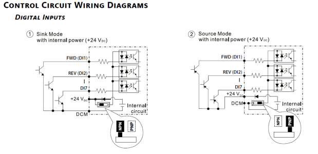
I have my switches mounted and connected according to this diagram. P002.00 is set to 3
I had P00.21 set to 1 but I didn't see any change, so I put it back to default. I never changed P00.20
I found a small stupid mistake I had made in the past and forgotten about though. For some reason, I had moved the source/sink dip switch to PNP which screwed everything up. I'll see what happens tomorrow.
- Joined
- Jun 12, 2014
- Messages
- 4,814
I had programming issues when I first setup a GS21, I had to reset everything back to the factory default and then sequentially make the changes and test them at each step. Source/Sink should not have an effect unless you are using it to power a LED lamp or using logic diodes.
- Joined
- Dec 14, 2018
- Messages
- 629
I think the Source/sink issue was because I was using the DCM terminal when the dip switch was in the PNP position.
This brings up another question though. I have a E-stop switch that I have inline on the lead going to DCM, which I'm assuming is correct. Will I need to change to source mode for it to illuminate?
And, I too have reset this thing several times and started from square one. I've pulled a few hairs out on this one!
- Joined
- Jun 12, 2014
- Messages
- 4,814
Using the DCM connection on the E-Stop will work with for sink. The connections are different if you use source as shown below and the E-Stop would be in the +24 line. On using the internal power supply for say a LED, I would use NPN mode, the LED would be connected between the +24V terminal and the DCM, you can run it through a separate switch block on the E-Stop if used as a power indicator for live controls. LED bulbs in the switches normally do not have a polarity and are for a specific voltage (AC or DC). I did a build with a GSM-21, I used their software to program it and as mentioned took a few tries before everything worked the way I wanted. Every time I change to another VFD, it is like starting over again.


- Joined
- Dec 14, 2018
- Messages
- 629
Everything works perfect! I found a really stupid mistake I made that, I'm too embarrassed to even mention, was causing ALL my issues!
Anyway, Thanks mksj for all the help. I would never have found my problem for who knows how long.
Anyway, Thanks mksj for all the help. I would never have found my problem for who knows how long.
Last edited:

