VFD Question

Ed W

Registered
Registered
Joined
Oct 22, 2013
Messages
38
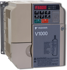
I have the opportunity to get a pretty good deal on a lathe. It has a 3-phase motor with a Yaskawa F7 VFD. The lathe will run on single phase, BUT the VFD is a 3 phase input unit rated at 2.2 kW. The motor is 3 hp. Am I correct that with single phase input the VFD needs to be derated to about 2 hp (VFD rated output at 240 v = 9.6 amps, the motor draws 8 amps; (9.6/1.732) divided by 8 times 3 = 2.08 hp)? Should I simply replace the VFD with a single phase rated Yaskawa (like a V1000) which is actually the same width and depth but shorter?
Any advice?
Thanks.
Ed
 
Last edited:
If you want to run it on single phase then I don't think a 3-phase VFD will work.
 
Actually it has run on single phase. This particular VFD model will work on single phase but my question is how much I need to derate the VFD and motor hp.
Ed
 
Hopefully @mksj will jump in here...
 
The derating for a 3 phase input VFD does varies by manufacturer, the general derating is to divide the rated amps by around 1.7, the range is 1.5-2.0 that is commonly used depending on the load and if you use a DC bus choke. Most current generation 3 phase input VFD can run single phase, the phase loss detection is usually based on the amount of THD (Total Harmonic Distortion) is senses. When running single phase there is much more ripple on the DC bus, a DC choke smooths the DC current pulses to the capacitors. If you look at some of the 4th generation Automation Direct VFD's they have even higher VFD deratings, like a factor of 2.5, so you still need to check on the manufacture's directions.

Most manufacturers either recommend or require a DC bus choke when using a 3 phase VFD with a single phase input. On my lathe I run a 3 Hp (2.2kW/8.4A) motor off of a 3 phase V1000 Yaskawa 5.5kW/19.6A VFD and use an 18A DC bus choke. I have two deratings for running single phase, the first is for running in Heavy Duty mode which brings the unit down to 3.7kW/17.5A, the second is derating for single phase so rating would be ~10.3A. I can move that higher with use of the DC choke and the parameter settings. There are also some deratings for ambient temperature and carrier frequency, most of these deratings assume full rated output on a continuous bases.
 

Attachments

  • Yaskawa Vfd derating 3 phase to single phase.pdf
    260.8 KB · Views: 7
Hi Mark,
Yes, I just saw that Yaskawa document. Given that Yaskawa only rates that F7 drive on single phase input for a 1 hp motor, seems to me it would make more sense to replace it with a dedicated single phase input drive, like a Yaskawa V1000 CIMR-VUBA0012FAA and use the entire 3 hp of the existing motor. Yes?
Ed
 
I should have indicated that you are correct, in that your current VFD would need to be replaced. I would use the V1000 model you have indicated, as there is some derating for HD use which is what I normally use on a lathe. I have purchased several VFD's from Motors and Controls, I recommend them if you want a replacement. I like the Yaskawa VFD's, you could use all the same wiring and also most of the parameter settings. The input breaker/fusing and wiring/power switch needs to be increased for single phase. I am using Bussman 30A Low Peak time delay CC fuses without problems and that connects to a 30A breaker at my main electrical panel. Input wiring is 10AWG 90C. Let me know if you have any questions on the install or need assistance with the parameter settings.
 
Thanks, Mark. Once I get the lathe and replace the VFD I may ask you for help with the parameters.
 
Hi Folks,

So I purchased the PM 1440GT 3 phase along with Mark's (mksj) recommended Hitachi WJ200-022SF VFD to bring 3 phase to it. I am just starting to dig into the conversion. Upon reading about the Jog command going into the VFD I seem to recall someplace in the manual the statement that the Jog input needs to be executed before the On (Forward or Reverse) is executed. This totally makes sense, otherwise the motor might already be running i.e. if the On command were executed prior to the Jog command. The manual also says the motor should be off before the the Jog is activated. So I have two questions and I have not been able to find the answers in the WJ200 manuals (yes, there are more than one version of these). Also, the answers are most likely specific to this VFD and not generic.

1) How much earlier does the Jog input signal need to arrive at the VFD input prior to the On signal or can they arrive essentially (nano-seconds) at the same time? (I am not talking about signals going to relays and then to the inputs as relays always introduce a significant delay time.) My guess is that these 7 VFD input terminals are all tied to one 8bit(?) I/O port of the VFD micro-controller and so they are all polled at the same time. If not then I would think that a required delay time between the Jog signal and the On signal would be at most one polling cycle. (While I found comments and uncalibrated wave form sketches I did not find any typical electronics timing requirements in the manual. If one event has to happen before another the timing windows are usually provided. Maybe it is in a different spec doc that I have not found yet?) My own experience with micro-controllers, tells me that there has to be VFD de-bounce timing built into the VFD software to insure a true reading and debounce times are usually a few 10s of milliseconds for mechanical switches (or relay contacts). A single cycle of 60Hz is 16.7 millisecond and we are driving a bit slow motor so there should be no rush in the VFD micro-controller to make a decision as to what to do with an input signal. Debounce algorithms usually do something like... look at an input, wait a debounce time, and then look at it again to insure that it has not changed. If it has changed it is not a valid signal so measure some more. To determine if a switch has opened a similar debounce process is used.

2) Is there any reason that two inputs cannot both be assigned to the same physical function, with for example different attributes like acceleration time. For example, can one program input 1 and input 5 to both activate the ON Forward command? If no one has tried this I guess I will just have to experiment, but would prefer to hear from those of you who might have experience with this already. The second part of this is then to know what happens when both inputs get activated at the same time? Or, what happens if they are both active, but one is turned off before the other. It is not obvious that one can or cannot do this, it is just a question of how the micro-controller code inside the VFD is written to handle it. Clearly, one has a Forward input and an Reverse input, but what happens if they are both turned ON.... the manual says that the motor does not turn on and I assume that if one is ON to cause the motor to be running and the other is then turned ON that the motor will either continue to run or it will shut down, but at what de-acceleration rate?

PS. My first complaint about the WJ200-022SF is its physical size! It is too long(depth) to fit easily into the PM 1440GT electronic hole in the stand base! It is too bad the hole is not 3 inches deeper. There is essentially nothing behind the welded back plate of the 1440 to have prevented it from being deeper. I will figure out a way to put it in with the rest of the electronics... somehow. I see that Mark (mksj) showed it located behind that plate, and I had thought of that, but it is not very satisfying as it will not pull out with the other electronics... and I do not know how much oil and other dirt will get in there! In fact, I really do not see why equipment makers feel that they need to put the electronics in the back at all. These machines seldom sit out in the middle of a room so that the back is just as exposed as the front. In my case it is up against a wall meaning you have to move the lathe to work on it.

Thanks,
Dave
 
The WJ200 does not require a delay between the jog/run command, they are both executed at the same time. So either you need two switch blocks (one for the run direction input and one for the jog input) or you can use a pair of diodes with a single switch block for each jog direction, the diode just prevent pack feed of the run command to the jog input with the normal run command. Other/most VFD's have a separate programed input that is for jog with a direction (F/R), the drawback is that you requires an additional input if you want both F/R run and F/R jog functions. A situation which rarely is used in lathes, but is requested when individuals want a forward/reverse jog when adding a VFD. Please not that all the JOG input does on the WJ200 is just set a fixed speed frequency which over rides the speed pot or any other speed settings.

Multiple inputs can and need to be active at the same time for certain functions. Two inputs cannot be assigned the same program parameter/function that I am aware of, but they can be each be programmed for different functions (or different allowed variations of a function) that do the same action. So for braking you can have a stage 1 and a second input for stage 2 and individually program the braking rate for each input. You cannot have two separate inputs for stage 1 braking and each with a different time specified. Certain VFDs allow you to use both braking or acceleration inputs to give you a combination of 4 rates depending on which input(s) is active (binary). Some inputs can be used as additive or subtractive when used in conjunction with other inputs. So like the multi-speed inputs are a binary addition to set the speed. There is hierarchy to one command over riding another, if you try to activate say both the forward and reverse input at the same time, the VFD will not issue a run command. Certain program functions need you to perform a VFD reset either from the front panel to programmed input to get the VFD back into a run mode. Most of this is described in the manual, but varies by VFD manufacturer.

As far as control panels and VFD locations, manufactures figure you will hookup the power to the control box and that is it. I always recommend enough room behind the lathe to at least get the door partially open and also to clean up chips/swarf. The control panels are typically NEMA 1 so keep out swarf and likely not get contaminated when located on the back of the headstock. As far as VFD mounting, I doubt they factored that into the mix given they have been using the same designs for many decades. I have done several 1440GT VFD installs, most have a separate VFD cabinet against the wall, but in 3 the VFD was mounted vertically in the headstock cabinet. There is plenty of room but the VFD does need to be mounted to a flat plate and some 90 degree brackets to attach that palte to the headstock cabinet internal wall. Also needs an external braking resistor mounted to one of the internal cabinet walls. A few people have put some form of shield over the top of the VFD 3-4" above it to prevent swarf falling down. An alternative to the WJ200 is the Teco E510 NEMA 4 VFD that can be mounted on the exterior of the cabinet and does have an internal power disconnect switch. I can provide suggested programming parameters if someone wants to take that route.
 
Back
Top