Voltage reduction of a DC motor

I apologize for waxing so verbose above. The subject is deep and I will expound on the subject for hours if I can.
Do not apologize, Bill. Your life's experience is hard earned. I surely appreciate you taking the time to help educate those of us less knowledgeable.
This sort of knowledge is not common, or easily transfered.

Thank You.
 
  • Like
Reactions: Z2V
P1020740.JPG
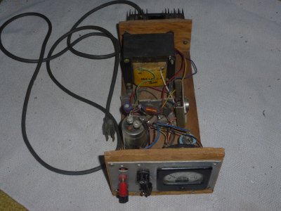
Above is a photo of a variable power supply I built using an LM317 voltage regulator. The meter on the front
panel is from an old volt-ohm meter shunted to read in volts. It was built breadboard style and
uses a variable resistor to control voltage output. The bridge rectifier part was fashioned from four diodes
extracted from an old car alternator. The 317 regulator(TO-3 package) is visible behind the meter mounted on the
bent aluminum heat sink. I find the variable power supply very handy for charging batteries as one can
easily control the voltage and thus the current the supply will impart to the battery. The unit easily
will supply 8 amperes at 12+ volts.

P1020741.JPG
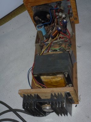
This photo exposes the power transistor used to handle the heavy currents. The resistors wrapped with copper
wire were made to create the low resistances needed for the circuit. Behind the transformer one can see two
of the diodes of the four mounted on 1/8 inch aluminum plate. The circuit is quite straight forward and the
breadboard design makes for an easy build. Most of the parts were from salvaged electronic junk. If the
spirit moves me, I will mount the unit in a nice metal cabinet. If I require a current reading, I connect an ammeter
in series with the output, an addition that I would use if I mount the supply in a metal box.
 
Regulated d.c. power supplies are fairly simple to make with available integrated circuits. Much more so than the bad old days. A less well known use of the LM317 and its larger sibling , the LM350 is as a current regulator. I made up an anodizing supply capable of supplying a regulated anodizing current from 0 to 40 amps. The TI data sheets offer a number of useful applications at the end. They simplify the design of a custom supply.
 
View attachment 322508
Above is a photo of a variable power supply I built using an LM317 voltage regulator. The meter on the front
panel is from an old volt-ohm meter shunted to read in volts. It was built breadboard style and
uses a variable resistor to control voltage output. The bridge rectifier part was fashioned from four diodes
extracted from an old car alternator. The 317 regulator(TO-3 package) is visible behind the meter mounted on the
bent aluminum heat sink. I find the variable power supply very handy for charging batteries as one can
easily control the voltage and thus the current the supply will impart to the battery. The unit easily
will supply 8 amperes at 12+ volts.

View attachment 322509
This photo exposes the power transistor used to handle the heavy currents. The resistors wrapped with copper
wire were made to create the low resistances needed for the circuit. Behind the transformer one can see two
of the diodes of the four mounted on 1/8 inch aluminum plate. The circuit is quite straight forward and the
breadboard design makes for an easy build. Most of the parts were from salvaged electronic junk. If the
spirit moves me, I will mount the unit in a nice metal cabinet. If I require a current reading, I connect an ammeter
in series with the output, an addition that I would use if I mount the supply in a metal box.
When you decide to enclos your power supply, a digital volt/ammeter like these https://www.ebay.com/sch/i.html?_fr...led+voltmeter+ammeter+amp+volt+meter&_sacat=0 make a nice addition. Ihey have an autoranging feature for voltage and current, providing at least two digit displays The supplied current shunt provides a low drop in output voltage. I have used them on the last four power that I have built.
 
Thanks, RJ. I will keep that in mind
when I get to enclosing my supply.


rj
 
the breadboard design makes for an easy build.
@ cathead
I see boards (wooden) but nothing that I would call a breadboard. Would you enlighten me as to what you call a breadboard please?
Aaron
 
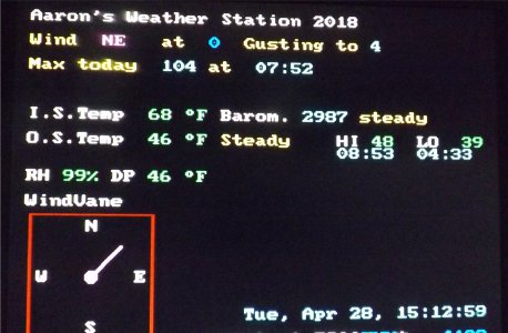
Got it. I use the modern plastic plug in ones and perf boards all the time. Never realized where the name came from. Here's my weather station.
DSCF4331.JPG DSCF4333.JPG

Thanks for new knowledge!
Aaron
 
@ cathead
I see boards (wooden) but nothing that I would call a breadboard. Would you enlighten me as to what you call a breadboard please?
Aaron

Sure.

Back in the old days of radio, radio receivers and even early transmitters were built on boards that
they called breadboards. I suppose one could argue that they just used a suitable board and called
it breadboard construction or quite possibly a real live breadboard was used. Wood is relatively insulative
so works fine and is easy to mount parts on. Myself, I just use any suitable board and call it breadboard construction.
Once the parts are mounted on the board, the circuit is wired up using a soldering iron and insulated copper wire.
In later years commercial radios began to use a shallow metal box so most of the wiring was underneath the top plate.
After that came circuit board technology.

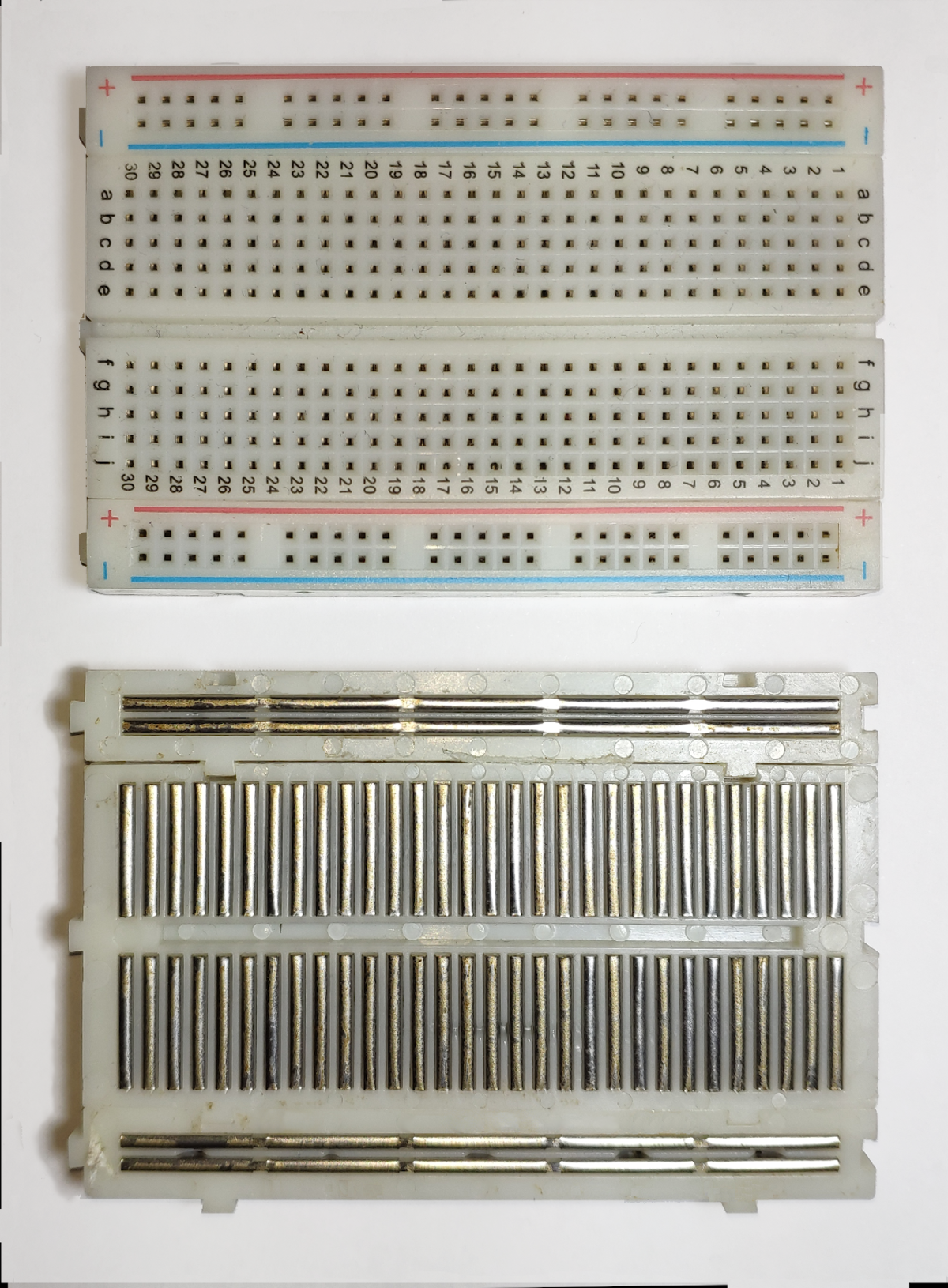
I see the plastic plug in boards decided to use the breadboard name too.:rolleyes:
 
Last edited:
Hobbyists use the term breadboarding for many types of electronic construction.

At times I will use a phenolic board with holes spaced about 3/16 inch apart. It's called perfboard.

Another method I use occasionally is to use a solid copper circuit board and use cyanoacrylate to
glue 1/4 inch square pieces of copper circuit board for connection points. The copper board is
used as ground so parts can be attached anywhere handy on the copper board. I call it pad
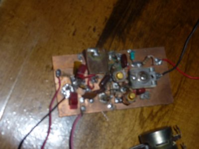
construction. Here is a photo of an RF oscillator using pad construction. It's handy for making
one board or for prototypes.
P1020742.JPG
The photo isn't the best but gives one an idea of how pad construction is done. On the left side of the
board on the front about an inch from the left is a pad visible with a red wire attached to it.
 
Back
Top