Ways to make a crank shaft

OK, I took all of the information I could find and what I gleaned from this site and what you guys here told me and decided that the larger counter balances probably weren't necessary and would only make it more complicated for me. Since this is my first engine build attempt, I also decided not to make anything too complicated and will only build a one cylinder engine instead of the two I originally thought about. That being said and decided, I set to work this past weekend in amongst the time I had to spend doing less important (in my mind) stuff to keep the homestead running and the war department happy. I am going to attempt to attach pictures of my progression so far and would welcome any comments. The parts are all press fit together and seem to be fairly well aligned, at least until when I cut out the currently through running main shaft. Will what happens then, I don't know, but I may have to do some straightening. This crank is for a 2" stroke, the rest of the engine design has yet to be worked out, but will likely be designed as I go and documented so I will be able to learn from my mistakes (and hopefully some successes). I already learned some thing by making the main shaft twice.
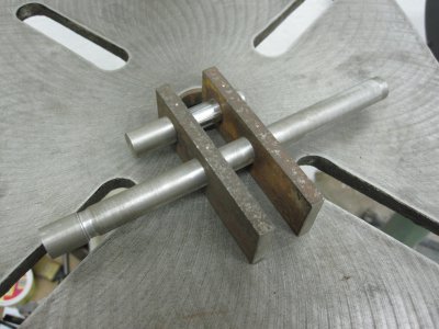
Pieces and parts ready to assemble.jpg

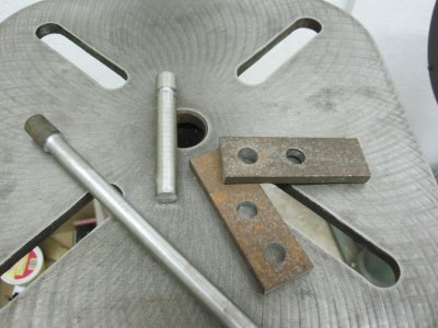
Here are the pieces and parts ready to be pressed together.


Parts pressed together.jpg

Pressing completed and everything seems to be aligned nicely.


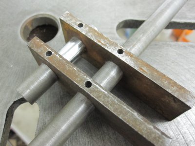
Pin holes drilled through.jpg

Through holes drilled for securing pins.

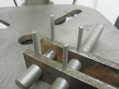
Pins ready for pressing.jpg

Pins ready to be pressed into the holes.

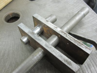
Pins filed flush.jpg

Pins filed flush.

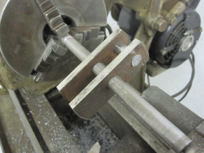
Below is the crank mounted in the lathe to round and even up the webs.

That's where I ended up the weekend.Webs rounded to look nice and be even.jpg

Pieces and parts ready to assemble.jpg Parts pressed together.jpg Pin holes drilled through.jpg Pins ready for pressing.jpg Pins filed flush.jpg Webs rounded to look nice and be even.jpg
 
Yep, that "orter" do it. At tip: drill rod and a set of over and under reamers. Almost make life too easy. I'm going to ream all holes one under, file a piece of drill rod to be a sliding fit and use it to align everything while pressing the rod journal. Then press the full sized main journals.

Hope it works. I'll always think it should have.

Bill
 
The only thing I would have done differently would have been to use Taper Pins to ease disassembly if it's ever needed. Your wall will work fine I am sure. ------ "Billy G"
 
For the last 150 years there have been engineers who made careers out of how to balance recip engines. Even with modern digital analysis techniques, it is not an easy task. The problem is that you have to balance several sources of imbalance - the most significant of these is the rotating mass and the reciprocating mass. On a single cylinder engine, the rotating mass can be balanced almost completely. The reciprocating mass is more difficult. A further complication is that the connecting rod is partly rotating and partly reciprocating. The large engines that you saw at the Ford museum make no attempt to balance with crank weights. Instead, they transfer the imbalance forces to massive amounts of cast iron structure and concrete foundations to minimize the accelerations and displacements of the machine as it runs. The old text books contain pages of calculations on how to size bearings, floor bolts and other members to safely transfer the imbalance loads to the mass.

So, one solution for the model engine is to ignore balance and clamp the model to a heavy table.

Otherwise, for smaller, single cylinder engines, the massive solution is generally not available. An example is "farm" or traction engines you see at threshing demonstrations. Model engines are an even more extreme case. Balancing a model sized engine is more like balancing a small lawnmower engine or a chainsaw engine.

The technique that dataporter describes below is known as "overbalancing." The idea is to increase the mass of the crank balances to partly compensate for the rotating portion of the connecting rod as well as the reciprocating forces. Traditionally, you assume that 1/3 of the connecting rod mass is rotating and 2/3 of the rod is reciprocating.

I am accustomed to seeing an equation a little different than what Dataporter shows below.

Balance weight = (weight of rotating parts + 2/3 weight of reciprocating parts) * (Radius of crank / Radius of balance center of gravity)

For the rotating parts you include the crank pin, the crank cheeks on the pin side of the shaft, and 1/3 of the connecting rod weight. (1/3 is not magic, it is based on experience)
For the reciprocating parts you include 2/3 of the connecting rod, and all of the cross head, piston rod and piston.
In traditional design you place 1/2 of the balance weight opposite of each crank cheek. (since you are using a double sided crank)

Since you are doing a "design - build" you don't know all of the weights yet, but you can take a guess at them. I would recommend leaving provisions to add balance weights to the crank after the design is completed. Drill & tap holes in the balance sides of the cheeks so that you can optimize the balance after the design is completed. Leave enough room in the crank case design to handle the diameter and thickness of the balance weights. To get a relative idea, look at the balance weights on the crank of a small gasoline engine. Then consider that the steam engine has addition recip weight in the form of the piston rod and the crosshead.

There is another source of unbalance - the valve mechanism. I am guessing that you will use an eccentric type of valve action. The eccentric, along with the connecting rod, also generates some imbalance. The traditional solution is to not attempt to balance the eccentric, but to keep the radius of the eccentric as small as the valve design will allow, and then to minimize the weight of the eccentric and the "strap." The valve loads are much smaller than the piston loads, so a lighter connecting rod can be used, and it can be made of aluminum to reduce the weight. (Another note: when you get to the valve design, consider a "piston" style valve over a sliding valve. The piston valve might be easier to make, and it takes less force to run it than the sliding plate type of valve.)

A further source of balancing happens with the valve timing. The steam valve always opens a few degrees before top center to assist in decelerating the piston and other recip mass. Likewise, the exhaust valve closes a few degrees before bottom center to generate "compression" and help to decelerate the piston and recip mass. The final compression on the exhaust stroke also slightly increases the efficiency of the engine because of thermodynamic reasons.

You are right in observing that low speeds make for less unbalance forces. The forces due to unbalance go up with the square of RPM. If the first engine dances around too much, consider it a learning experience when you start the second.

Sorry for the rambling post.
Looks like you have a fun and interesting project.
Terry S
 
The only thing I would have done differently would have been to use Taper Pins to ease disassembly if it's ever needed. Your wall will work fine I am sure. ------ "Billy G"

Billy, at first, I thought the same. But on second thought taper pins in a blind hole are not particularly user friendly and if you through drill, the straight pins will come out just fine.

Bill
 
I didn't see that yours were blind holes. In your case that is the way to go with pins. I can't imagine trying to properly fit a taper pin in a blind hole. ------ "Billy G"
 
The pin holes were through holes with an interference fit and they are made of the same metal as the webs so if worse came to worse, they could be drilled out. All parts were set up as interference fit and pressed to position. The pins were just the lock to assure nothing moved, since I don't have the ability to silver solder yet.

I like the idea of putting some tapped holes on the crank webs to allow for the addition of mass later. I might even just add the mass now with the idea that it could be reduced later. Does the mass of the flywheel help to stabilize the inbalances in the rotating and reciprocating masses and can you add balancing mass to the flywheel to offset the crank imbalance?
 
The flywheel is there to take out the torsional oscillations that come with a reciprocating engine. The piston delivers very low force to the crank near the end of each stroke, and flywheel carries the crank through to the next steam injection.

The flywheel is usually made to be balanced by itself and does not contribute to removing balance issues on the crank.
The reason is that the flywheel rotation plane is usually set some distance from the plane of the crank. Placing a balance weight on the flywheel to address a crank imbalance will introduce a "couple" along the crank shaft which will introduce another mode of vibration.

The exception to this is found on small engines such as pumping engines or hoist engines where the flywheel has the crank pin cantilevered directly off the flywheel. On these small engines it is sometimes hard to decide if it is a crank pin on a flywheel, or a really big, counterbalanced crank - with no flywheel.

The old steam engineering textbooks usually have an entire chapter on flywheel sizing and design. Depending on the scale of model you are building, your flywheel design might be limited by the swing on your lathe.

There is a section on the forum designated to "Live Steam." Perhaps you have already looked through some of the posts there. Some of these builders have ingenious solutions for problems encountered with building model sized engines.

Terry S.
 
Would it be possible to mig weld extra mass onto this crank, by drilling holes in the extra bits, and welding down through the holes onto the outside of webs that are a part of the crank as it currently is? Would the heat be too much and cause the crank to warp or otherwise deform? Does anyone have experience with this sort of thing?
 
I have no experience with such a thing, but would not even think of doing so, especially while in close proximity of the crankshaft. Such thoughts might cause warping!

Bill
 
Back
Top