What's acceptable for accuracy?

Drill rod looks accurate,but it is not as accurate as you might think. It tends to be "lobed".rather than perfectly round. I can't recall how lobed it is,but it is not a standard of accuracy that you should expect to be perfect.

So, what CAN be used, that would be more accurate than drill rod? Thanks, JR49
 
Dave, if you want to check squareness of a face, cut a disc, and then run a test indicator across it. Should read zero across the front, since that was the cutter path, but past center it will show any deviation from square. Actually it will show 2x, but ideally, it will be zero from front edge to back edge. No need for a straightedge. It will show a cone if the cross slide is out of square with the ways and or the headstock.

Tony,
Thanks for the information and great description. Makes perfect sense, hadn't thought of it.

Dave
 
So, what CAN be used, that would be more accurate than drill rod? Thanks, JR49

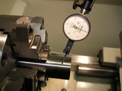
You can use the shank of an endmill, reamer, pin guage, etc., something that has a precision ground surface. I use Thomson linear shafting to dial in my Set-Tru chuck. I have 2 sizes and use them accordingly when I know I will be working more often closer to one of those sizes.


Img_6417.jpg
 
Drill rod looks accurate,but it is not as accurate as you might think. It tends to be "lobed".rather than perfectly round. I can't recall how lobed it is,but it is not a standard of accuracy that you should expect to be perfect.


You got me remembering the good old days. A VERY long time ago. I supervised a grinding shop. We had a centerless grinder and if it was not set-up correctly it would grind a shape similar to the Wankel rotor and not round. Can’t recall the problem in set-up that would do it. Can remember that if you took a standard two point measuring mike it would read round at any point. But, if you took a three point mike, then you would see the error in roundness.
 
Dave, if you want to check squareness of a face, cut a disc, and then run a test indicator across it. Should read zero across the front, since that was the cutter path, but past center it will show any deviation from square. Actually it will show 2x, but ideally, it will be zero from front edge to back edge. No need for a straightedge. It will show a cone if the cross slide is out of square with the ways and or the headstock.

Tony, I also appreciate your great how-to, but it brings up yet another question that I didn't even realize I needed to know. If the cross slide is "out of square with the ways", how would this be corrected? Thanks, JR49
 
Well, if you have confirmed that the spindle is parallel with the ways, independent of the tailstock, then the only real solution is to do a bit of scraping on the cross slide. Normally, more wear shows up on the -Z- axis, so it's likely where the problem originates if the cross slide was square with the Vee ways to begin with. Since most of the flat facing of any size where it might really make any difference is near the chuck, the cross slide ways would be my choice of a remedy. Recognize though, that as you move away from the chuck for longer parts, you may lose some of this squareness, provided the error was truly introduced in the -Z-axis. If you are doing a 100% accurizing of the machine, after the -Z- axis ways are dead on with the spindle, in both planes, then I would address the cross slide squareness. And then last, the tailstock for height and -X- axis position. Then for tailstock quill alignment. Some machines have a large pin the headstock pivots on, and people sometimes overlook this as an adjustment for spindle parallelism. If your machine has that provision, use it.

In reality, most of us won't be machining any plane mirrors, and the faces machined will be relatively narrow. It would be an extreme case where it would be a real concern. If it were, scraping/lapping would be in order. This is just my personal opinion, fwiw.
 
I got a piece of 1 3/4 junkyard steel and turned it between centers. It tapered .002 on 22 inches. I'm pleased as punch with that. Next I'm going to cut the shaft to 12 inches and make a dumbbell by pressing on a pair of 3 inch x 1 inch aluminum discs. Once I get them turning within .001 I'll save it for a test bar. I don't have a taper attachment so I thing the easiest way to offset and rezero my tailstock is to have a test bar that can be indicated from my carriage.
 
The accuracy of what you stated sounds great.

By all means try to work to the best appropriate precision you have available when necessary but most things just don't require absolute precision and accuracy. In general, you start chasing your tail about accuracy. With every part it is a combination of it's required accuracy and the acceptable tolerance. You have to know when to let go. The best way is to have the tolerance set before you ever start building a part. You decide it by the accuracy needed by the part, the capability of your machines (or hand work) and the measurement tools and techniques you have available.

Very few projects require more than one or two dimensions that require more than a couple thousandths accuracy. Other than measurement tools, it is really rare that something really requires a measurement to more than half a thousandth. Getting to tenths and beyond, you start needing a lot of specialized things like clean rooms to really work at that level consistently. Having a measuring device that will read in tenths doesn't mean you have an environment without contaminants and at constant temperature to make the measurements valid.
My goal is to make a test bar to re-align my tailstock accurately and quickly after cutting a taper so it would only make sense to make that bar as accurately as I possibly can, no? Like they say at the rifle range, "aim small, miss small". That said, I was delighted to learn from this thread that my machine has acceptable accuracy. The jury is still out as to whether or not I can make the same claim for the operator. Thanks for the help.
Ed P
 
It's possible to have much better repeatability (which is what I think you want for your test bar) than accuracy.
 
Back
Top