Who owns a Grizzly 4003 lathe from 1999 to 2005 ?

In comments below, I am only talking about the left two (Red plunger) contactors and ignoring the right 3rd contactor (Yellow Plunger).

Both the two left contactors are wired through each other
So Left contactor un-energized 21NC connects to 22NC which should feed over to A2 (or A1) on the right contactor
So right contactor un-energized 21NC connects to 22NC which should feed over to A2 (or A1) on the left contactor

This is a protection so if you are in forward (say left contactor is energized) this opens the contact 21NC to 22NC on the left contactor which breaks the ability for the right contactor to operate and vice versa.

You should have a traceable wire that feeds from each of the two left contactors out to your control switch.

Lets start by finding them


control switch (drum switch?)
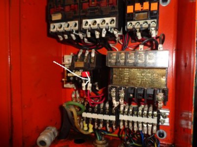
Here is a picture of the electrical panel

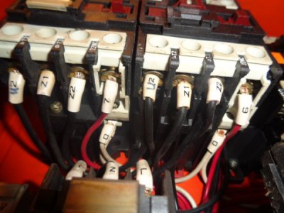
Both contactors are identical
top left to right on each contactor are numbered as follows.
L1 L2 L3 NC21
bottom of both contactors are marked
T1, T2, T3 and NC22
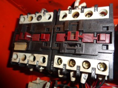
DSC02853.JPG
I finally found A2 (see don't see anything that is marked A1)
U2 Z1 and Z2 all jump over to the same terminals on thht contactor
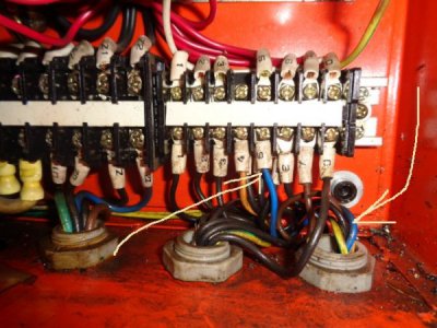
#7 red wire feeds all the way down to the lowest right part of the cabinet, what I would call a power strip
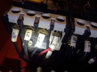
DSC02854.JPG
Red #6 also goes to power strip.

DSC02855.JPG
I bought this lathe brand new in 1999.
Today is the first time the inside of this electrical box has EVER seen a screwdriver
 
All of the information I am providing it based on the current diagrams. I am assuming they are the same for your vintage.
It appears the colors they are using are not the same.

Ignoring the green and yellow (earth) there are four wires two should go to the two left contactors, one should come from the power start switch and one should go to the 3rd contactor.

2 wires to the left contactor or one wire to the left contactor and one wire to the middle contactor?
 
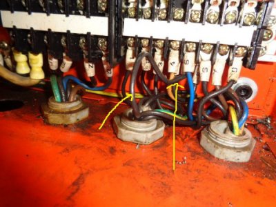
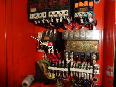
I traced the blue wire from this harness (goes to the drum switch). It comes from the drum switch harness into the bottom right of the ele. box as seen here, loops around and connects to the "power strip?) as seen by arrow
.DSC02856.JPG
it has a black jumper wire also on that terminal which goes down into the motor
DSC02857.JPG
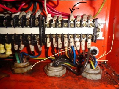
if you look across the terminal board from this blue wire, there is a red wire (black arrow)
DSC02856.JPG
if ya trace this red wire, it leaves this terminal strip and goes to this one
DSC02859.JPG
this also has a jumper, which final end is here, on the right (yellow plunger) contactor
circled in blue
DSC02859.JPG
 
Sorry for the delay, movie night,

The blue should go through the overload relay and then over to the 3rd contactor that is the latching wire. The overload relay will disconnect that if the motor is stalled

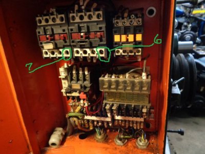
The number 7 and number 6 wires at the two contactors are the forward and reverse wires, find out what colors they change to at the terminal strip

#7 red wire on far left contactor and #6 red wire on center contactor

DSC02893.JPG

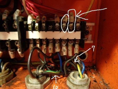
These 2 wires terminate here on the power strip.

Directly across the strip, #7 is the BROWN wire in the harness that leads directly
to the new drum switch. #6 is a black wire that goes straight down to the motor
.DSC02894.JPG
 
I am not sure what you have going on because it does not match current wiring diagram,...
but we should be able to figure this out.

At the forward reverse switch wiring,

Ignoring the green and yellow (earth)

We should be able to narrow down the one from the power start switch because you should get a voltage jump on one of the four wires when the power start switch is pushed. So with eStop switch on (out) and a voltmeter on AC connect to each of the four wires one at a time, and then momentarily put the power start. One of the four wires should show a voltage jump (probably 110v),

If none of them show a voltage jump we will stop here and look for other problems.

If that works, you can then determine which is the forward, reverse and 3rd contactor by holding the above found wire to each if the other 3 one by one and pushing power start, One should operate forward, one reverse and one should latch the 3rd contact.

If all of the above works, You should connect the first found power switch wire to the the 3rd contactor wire. Now when you press power start the 3rd contact should latch on and stay on until estop. Now you should be able to touch either the forward or reverse to the two connected and get forward and reverse.

Let me know how this goes.

The red lead of the AC volt meter to each of the 4 wires that run to the drum switch, the black lead of the meter to ground?
I am not sure what you have going on because it does not match current wiring diagram,...
but we should be able to figure this out.

At the forward reverse switch wiring,

Ignoring the green and yellow (earth)

We should be able to narrow down the one from the power start switch because you should get a voltage jump on one of the four wires when the power start switch is pushed. So with eStop switch on (out) and a voltmeter on AC connect to each of the four wires one at a time, and then momentarily put the power start. One of the four wires should show a voltage jump (probably 110v),

If none of them show a voltage jump we will stop here and look for other problems.

If that works, you can then determine which is the forward, reverse and 3rd contactor by holding the above found wire to each if the other 3 one by one and pushing power start, One should operate forward, one reverse and one should latch the 3rd contact.

If all of the above works, You should connect the first found power switch wire to the the 3rd contactor wire. Now when you press power start the 3rd contact should latch on and stay on until estop. Now you should be able to touch either the forward or reverse to the two connected and get forward and reverse.

Let me know how this goes.


Ok, so I checked that this evening.
E stop switch out, drum switch in off position,
black lead on AC volt meter to ground on lathe
red lead to #7 brown wire 20v as is, 30 volts with power button pressed in
red lead to #6 black wire 20v as is, 30 volts with power button pressed in
red lead to #5 blue wire 4v as is, 11 volts with power button pressed in
red lead to #4 orange wire 10v as is, 86 volts with power button pressed in
 
ok orange must be the feed from the power start.

If you connect 4 to 5 and push power start does the 3rd relay latch?
If you connect 4 to 6 and push power start does it operate forward or reverse (opposite of 4 to 7)?
If you connect 4 to 7 and push power start does it operate forward or reverse (opposite of 4 to 6)?

If the above works, on your drum switch,

You would want 4 to 5 to be connected only when drum switch is in off position
You would want 5 to 6 to be connected only when drum switch is in forward or reverse ( which ever direction you determine from above)
You would want 5 to 7 to be connected only when drum switch is in forward or reverse ( which ever direction you determine from above)

Hope this helps
Are ya saying connect 4 to 5 with just a jumper wire for testing purposes? And this is done on the drum switch?
 
Back
Top