Why Would I Need A Quick Change Lathe Gear Box?

Well, durn, Susan! I live in the Phoenix area myself, and know Neil from the Valley Metal club. Fantastically nice guy, isn't he? I would have really enjoyed meeting you. Give a shout next time you plan a trip out here.
Hman, this is awesome. Now we have an excuse to go out and get some drinks! I visited AZ also since my best friend from high school now lives in Phoenix.
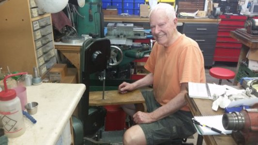
Here's a crazy pix of Neil showing me how he "rides" his horizontal bandsaw, lol!
289724

Hey, I guess when you're older, comfort comes first.
 
About the Bridgeport / VFD / motor thing. Here with I share some opinions. You are power constrained - 20A @ 120V. Nominally 2400 watts. The VFD will not achieve the voltage change (120 -> 240). You have a 3000W transformer (single phase - I assume). Confirm the VFD is rated at a 240V input (which it probably is). So you connect the 120V side of the transformer to your supply (via a single pole disconnect) and the high voltage side to your VFD inputs.

Run your existing BP motor (mainly because it has the smaller current draw, it works fine for the machine - and it is ready to go). Keep leads as short as you reasonably can - that will reduce the harmonics (voltage spikes). The duty cycle on a manual mill is generally extremely low (few hours and generally lightly loaded) - in practical terms it is going to last a very long time. It will be up to you to operate the motor such that you keep a reasonable RPM so the cooling fan moves a bit of air (i.e. keep the motor speed up above 45 Hz if you are loading the motor).

I have a drill press with a 3/4 HP, 1200 rpm, 3 phase motor. It has class B insulation. I acquired a nice little VFD (vintage mid '90s) - it probably does not have the features of the newer VFDs - the drive and the motor are quite noisy. The VFD is close to the motor, the leads are short and I'm running the start/stop buttons into the VFD controls. The drill press performs very well.

Of course a higher rated motor would be nice, but the likelihood that the motor with class B insulation will fail because it is on a VFD is extremely small (if the motor insulation is that weak, it was probably close to failure anyway).

Let us know how you make out. David
David,
I moved my comment to the Bridgeport posting. I accidently typed it under my lathe posting.
I read your reply, but will read again. I will post my reply under the Bridgeport posting. Sorry for my mixup. I was typing quickly in my car - parked but still hurrying. I really appreciate your insight :)
 
Hi Guys,
As many of you already know, I have too many lathes (6", 9", 10"). I was happy having a South Bend 9A 9" lathe, then got the free Logan 200 10" lathe. Ideally, I would like to keep both lathes. The Logan does not have a quick change box.

Awhile ago, I bought this tailstock tap/die holder from a machinist online, Neil. On his website, there is a video on how to use his gadget.


Anyways, if I were to use this tool, would it matter if my lathe had a QC box or not?

Forgive me if the answer is obvious.

I am debating which lathe to keep if I were forced to keep only one due to lack of space (the Bridgeport mill literally takes up a thirc of my garage).

The Logan seems to have more mass than the South Bend, but is lacking a QC box.

Thanks,
Susan


I am on the third lathe I have owned (I still have the other two they were a lot littler)and it's my first with a quick change gearbox, I would never purchase a lath without a quick change gearbox now.

:)

Stu
 
You might recall my 3 cents on a lathe without a QCGB and has a flat belt(s) and etc, etc. Moving onto your die holder mounted in the tail stock. It will make threads but not always true to the shaft/project. It’s always better to start a thread with the lathe using your QCGB!!!! And then you can finish up with that die thing if so desire. Using the lathe to get the threads started will assure the “die follows” the unfinished threads instead of the “die leading” with no threads to follow and go astray.
 
I don't even have a QCGB and I still go to the trouble of manually changing gears just to use the threading feature of my lathe.

My lathe is also not "threading friendly". I have no thread dial on the lead screw. So the only way to thread is to keep the half-nut engaged throughout the entire process, which means that I need to reverse the lathe between every cut. I can't back up using the handwheel.

I'm looking forward to the day when I can buy a lathe that has a QCGB and a thread dial. In the meantime I've been cutting nice threads with the set-up I have. It is a pain though having to manually swap the proper gears out. But I'm getting that process down to a science so it's not too bad.
 
I don't even have a QCGB and I still go to the trouble of manually changing gears just to use the threading feature of my lathe.

My lathe is also not "threading friendly". I have no thread dial on the lead screw. So the only way to thread is to keep the half-nut engaged throughout the entire process, which means that I need to reverse the lathe between every cut. I can't back up using the handwheel.

I do it much the same way. I have a threading dial, but it's not always useful as I tend to cut metric threads as often as US Customary/Imperial, which is why I mostly prefer change gears. On the 1903 SF lathe. a 12TPI leadscrew and gears (18,24,26,30,36,36,42,44,46,46,54,60,66,72,78,84,96) allows me to match an absurd number of threads/feeds. I don't argue that a QCGB would be desired in a production shop where time == money, but shaving a minute or two off production time won't save me anything.

As for the threading dial, I suppose one could be fabricated if you can't find a used one; however, I don't find it to be a required accessory.
 
I do it much the same way. I have a threading dial, but it's not always useful as I tend to cut metric threads as often as US Customary/Imperial, which is why I mostly prefer change gears.

That's an interesting point. I know my lathe will cut both metric and imperial threads as I have cut both already, and the gear charts that came with the lathe include gear combinations for both metric and imperial thread cutting.

However, I'm pretty sure my lathe has a metric lead screw. The reason is because there are two gears that only come with the metric lead screw, and two gears that only come with an imperial lead screw. My gear set only includes the two special gears for the metric lead screw. So I guess my lathe has the metric lead screw? I could probably check the lead screw pitch with thread gauges to find out.

Would this then make a difference is I added a thread dial? Obviously if I have a metric lead screw I would need to make a thread dial with a metric thread to match the lead screw. But what then? Could the thread dial still be used when cutting either metric or imperial threads? Or would it only be useful for cutting metric threads?

Sorry for my ignorance, but I really don't know how that would work.

I'm assuming that if I get a lathe with an imperial lead screw that comes with a thread dial it would also cut metric threads? I don't even know how that works.

All I know is that my current lathe will cut either metric or imperial and I've been cutting both. So far I've done an imperial 3/8-16, a metric M8 x 1.25 and a M10 x 1.5 and they all came out perfectly. These were all covered in my thread gear charts. It looks like I can do most imperial and metric threads.
 
However, I'm pretty sure my lathe has a metric lead screw. The reason is because there are two gears that only come with the metric lead screw, and two gears that only come with an imperial lead screw. My gear set only includes the two special gears for the metric lead screw. So I guess my lathe has the metric lead screw? I could probably check the lead screw pitch with thread gauges to find out.

I'm not certain I am following in the discussion about the 2 gears (I suspect my limited experience is at fault), but do you not have a collection of gears which define the speed between the spindle and the leadscrew? It is my understanding that the thread pitch on the leadscrew itself, combined with the gears between the spindle and driven gear on the leadscrew, which defines whatever pitch will result. (edit: in my case, 17 gears of which 2 are duplicates)

Would this then make a difference is I added a thread dial? Obviously if I have a metric lead screw I would need to make a thread dial with a metric thread to match the lead screw. But what then? Could the thread dial still be used when cutting either metric or imperial threads? Or would it only be useful for cutting metric threads?

I think it would matter. I'd need to think and double check, but if your leadscrew were say 2.0mm pitch, the threading dial would only be useful for multiples and some divisions thereof. If the dial were divided in say quarters, I think it would match in 0.5mm steps.

Sorry for my ignorance, but I really don't know how that would work.
I'm guessing and hope if someone actually knows they will pipe up and inform us both!

I'm assuming that if I get a lathe with an imperial lead screw that comes with a thread dial it would also cut metric threads? I don't even know how that works.
It does, but as I understand it the threading dial is effectively worthless and you'd have to keep the half-nuts engaged to ensure catching the thread again. I think the threading dial would only be useful within the system that matches the threads on the leadscrew.

All I know is that my current lathe will cut either metric or imperial and I've been cutting both. So far I've done an imperial 3/8-16, a metric M8 x 1.25 and a M10 x 1.5 and they all came out perfectly. These were all covered in my thread gear charts. It looks like I can do most imperial and metric threads.

Mine has a tiny brass plaque with some imperial/customary threads, but I use a script I wrote to select my gears, usually in 3 or 4 gear combos where 2 gears are ganged on a spindle, driving the other two, which are connected to the spindle and the leadscrew. I've cut a variety of threads in both measures so I know it's accurate within tolerances.
289862

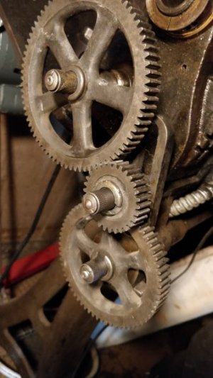
Where the top large gear engages the middle gear, which is locked together with a second, smaller gear that engages the bottom gear which is connected to my leadscrew.
 
Last edited:
By the way, that threading tool looks pretty easy to make.

Apparently all you need to do is make the following parts:

View attachment 289572

My tapping dies are hexagon anyway, so I wouldn't want round die holders.

I think I'd design the knurled sleeve differently. I'd make it quite a bit larger in diameter.

In fact, you could probably just put the tapping dies right inside the the end of the knurled sleeve instead of having separate die holders.

I can start with just three pieces.

  1. The tailstock arbor
  2. The Knurled Sleeve with built-in die holder.
  3. And a stop handle.
I could even start with just a round piece of stock for the tailstock arbor and hold that in a tailstock chuck

It's getting simpler by the moment. :grin:
I plan on making my own and have looked at several videos at different approaches....one approach is to take a hex die holder and cut off the arms and then turn the OD. make it a slight press fit with Loctite RED applied. Put some set screws in place through the hex and you are all set to go. This is one of my first projects to make figuring it would give me some good lessons to learn at the same time as I get a cool tool.
 
Back
Top