
Good Morning, I tried your suggestion. put the red and black wires back onto the motor terminals, the motor ran in one direction only. thats great. Then i got brave and attached the red and black to the switch and motor but it only hummed in both forward or reverseSorry, forgot to upload the sketch
Let me take another look at the Century diagram your wife sent, I might have missed something
Question: Are you getting a hum from the motor or nothing at all? Hopefully not sparks and flames
First test:
1) Disconnect drum switch 3 and 4. Put the red and black "rotation leads" back on to the motor 2 and 4 terminals. Keep the drum switch 1,2, 5 and 6 connected. Motor should run in one direction when switch is thrown forward or reverse.
I'm suspecting your drum switch might be at fault

-
Welcome back Guest! Did you know you can mentor other members here at H-M? If not, please check out our Relaunch of Hobby Machinist Mentoring Program!
You are using an out of date browser. It may not display this or other websites correctly.
You should upgrade or use an alternative browser.
You should upgrade or use an alternative browser.
Wiring drum switch
- Thread starter john shaw
- Start date
")
- Joined
- Apr 30, 2015
- Messages
- 11,318
OK then, sounds like the drum switch 3 and 4 terminals are not getting power as they should. If you have a multimeter you should see 120 volts ac between 3 and 4 in both forward and reverse. I would look closely at those contacts. Can you shoot a close-up picture of the drum switch and email it to me?
-Mark
PS be careful testing live circuits
-Mark
PS be careful testing live circuits
Last edited:
- Joined
- Apr 30, 2015
- Messages
- 11,318
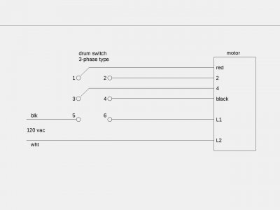
John: The switch is actually a 3-phase reversing type.
Connect it as shown and it should work for you:
(swap red and black if necessary to match rotation with switch handle)
Don't forget to use a 3 wire power cord, connect the green ground wire to both motor and switch cases
Connect it as shown and it should work for you:
(swap red and black if necessary to match rotation with switch handle)
Don't forget to use a 3 wire power cord, connect the green ground wire to both motor and switch cases
Attachments
Last edited:
John: The switch is actually a 3-phase reversing type.
Connect it as shown and it should work for you:
(swap red and black if necessary to match rotation with switch handle)
Don't forget to use a 3 wire power cord, connect the green ground wire to both motor and switch cases
John: The switch is actually a 3-phase reversing type.
Connect it as shown and it should work for you:
(swap red and black if necessary to match rotation with switch handle)
Don't forget to use a 3 wire power cord, connect the green ground wire to both motor and switch cases
Thanks for the drawing but i am confused over some of the wires. i understand the white line cord from the wall going directly to the motor L2 , black wire from the wall going to switch #5, line L1 going from motor to switch #6, black wire in motor going to switch #4, ( terminal #4 in the motor is where the red wire came from and has now been extended and connects to switch #4), my motor has no wire as you show as #4 and going to switch #3. my motor has no wire #2, only L2 and that is already in use as power from the wall . the red wire in the motor has been extended and goes to switch #1. i guess my big question is what do i do about line # 2&4 in the motor
- Joined
- Apr 30, 2015
- Messages
- 11,318
You need to add two wires to bring motor terminals 2 and 4 out. You could solder them or buy some slip-on lugs, your choice
- Joined
- Feb 13, 2017
- Messages
- 2,138
Part, a large part, of this message board is to help the novice learn something. Connecting wire A to terminal 1 is just following directions, not really learning anything. Let's back up a little bit and look at what you are trying to do. There are many reversing switches, drum switches, some manufacturers actually have different connections for different switches. So we will break down the reversing process into individual tasks. There are two (2) seperate but distinct things to be accomplished.
The first thing is to turn the lathe ON and OFF when the switch is operated. That's a fairly simple process, just a switch that operates when the operator is thrown in either direction. Find the deck of contacts that do that and mark it as such. Just a piece of tape will serve. We want to break the line cord BLACK wire in the off position. That will leave four (4) terminals open. It would be a good bet that the ON-OFF contacts are at one end (or the other) of the three.
The other function is to reverse the motor. The wiring is a little trickier there. The motor nameplate states that reversing the RED and BLACK wires on the motor will reverse the direction of rotation. The BLACK wire noted is not the BLACK wire of the line cord, it is an internal wire in the motor.
In home centers, there is a switch, called a "4 way" light switch, that will accomplish this. It is called a "4 way" switch because it has 4 terminals. Inserted in the "runners" of a 3 way switch, it allows another operating location. We are simply going to duplicate that switch with the drum switch. If you don't know electric circuit theory, a drawing would be meaningless. But basically, the switch thrown one way connects the terminals on one side. Thrown the other way, the connections are crossed. This is what you want to accomplish with the drum switch.
There are several ways to accomplish this, the most common for "old school" switching is to have two bars internally. When the bars are vertical, they connect one way. When they are horizontal, they connect the other. The OFF position is where no bars swing into position. We want to find the terminals, often across from each other on a diagonal, that will accomplish this.
You will need to provide a total of four(4) wires from the motor. Two for the RED-BLACK pair and two for the terminals that they connect to. This is in addition to and seperate from the line cord wires. There are ways to route the line cord through the drum switch and reduce the number of wires. But if you need 4 anyway, what's another couple? Keep it brute force simple and use the six wires bring the line cord into the motor so you can see what you're doing.
In the motor, the reversing wires are usually made up with 1/4 inch quick disconnects, called "Fastons". It is highly recommended that a couple of male/female pairs be acquired to make these connections. It can be done by cutting and splicing wires, but looks terrible and is another source of trouble. They are cheap enough, and widely available. A goodly part of what makes an electrician an electrician is doing good, "workman like" work. Making things look good is half the job.
.
I will give it a try.I want to thank you again. you have been very patient. if everyone would be like you it would be a better world!!!!!!You need to add two wires to bring motor terminals 2 and 4 out. You could solder them or buy some slip-on lugs, your choice
- Joined
- Apr 30, 2015
- Messages
- 11,318
Most folks have more important things to do than learn motor theory and magnetics; they just want to make chips. There is plenty of info available on Wiki if one wants to know more, so I usually just address the immediate need, and keep it brief
One of these days I will put together a definitive guide to hooking up reversing switches that will (hopefully) make anyone an expert
-Mark
I'm thinking 3 sections:
1) identifying your motor
2) identifying (or selecting) your switch
3) putting it all together
One of these days I will put together a definitive guide to hooking up reversing switches that will (hopefully) make anyone an expert
-Mark
I'm thinking 3 sections:
1) identifying your motor
2) identifying (or selecting) your switch
3) putting it all together
Last edited: