- Joined
- Oct 21, 2021
- Messages
- 63
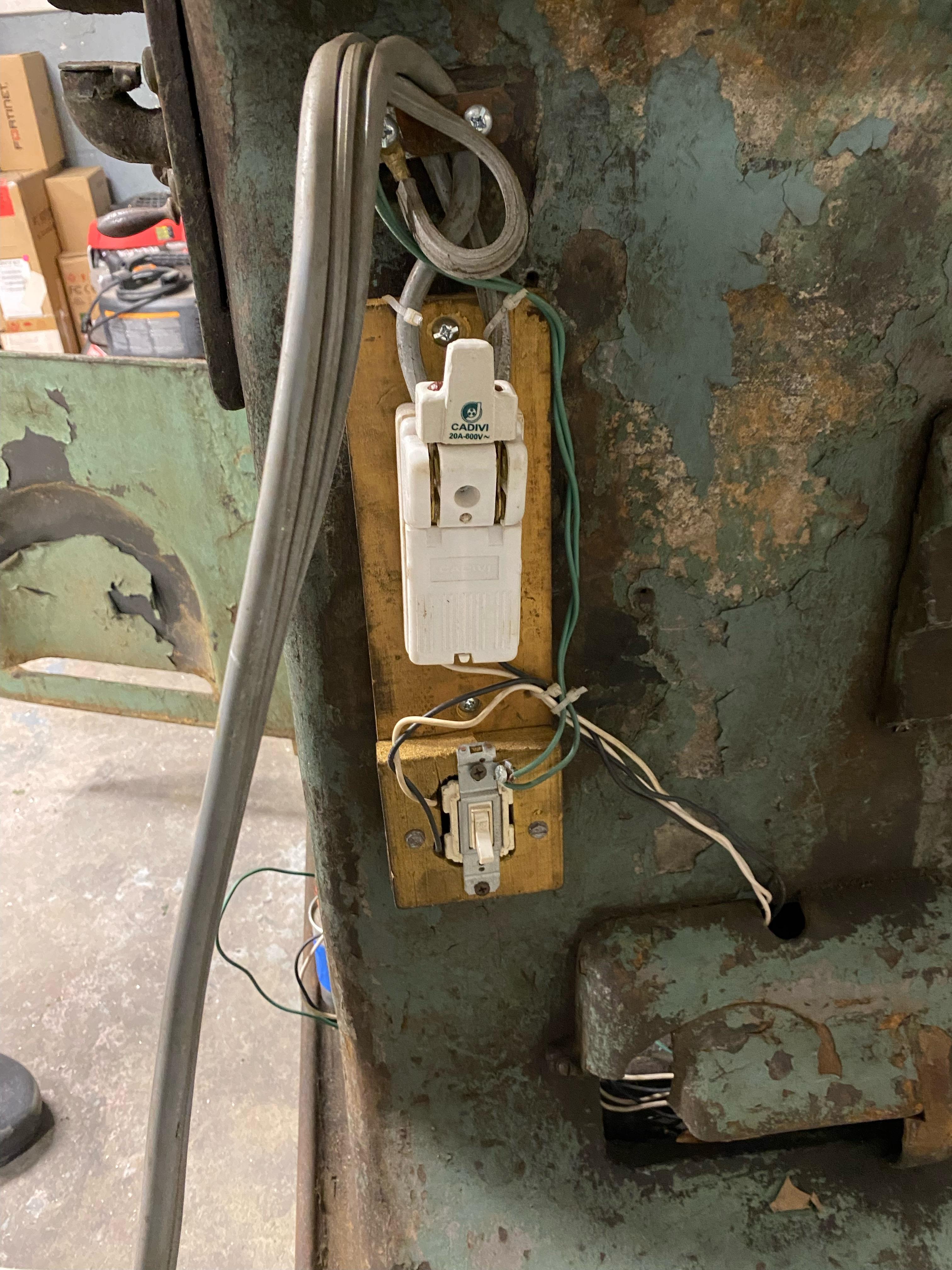
I'll grab some pictures of his switch setup tonight when I get out there. FUBAR is one way to describe it.wow, hot mess is right. He really fubared that .

I'll grab some pictures of his switch setup tonight when I get out there. FUBAR is one way to describe it.wow, hot mess is right. He really fubared that .
these grinders can't accomodate 25 cycle current (?!?)
25 cycles / HertzOne thing about the motor, I believe there's 9 wires coming out of the motor here, 3 tied off on blue, and 2 in each set on the white (x2) and black taped pairs.
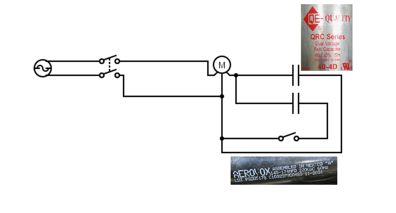
The 9 wires means that it is a dual voltage motor, likely 220 - 440 VThis is interesting, if I measure the draw with this SPC config running should I make that 2/3's adjustment? Could the capacitors that are in use tell me anything? Maybe just what he thought it was sized like? I have a note of 70uF per kW that I pulled from a youtube video or two I've watched trying to understand how its currently configured. Am I on the right track with that way of thinking?
This sounds like the way I will be going. I have/use VFD's for my Lathe and Mill already. The parts doc on Vintage Machinery (This one) actually lists an 8" x 1/2" disc wheel for this thing. See page 13. It looks like the 1-1/2 was a 1/2" disc thickness as well. As an aside - its crazy how old some of these machines are! I was just read about how these grinders can't accomodate 25 cycle current (?!?). And several references to 2-phase current. Back in the beginning days of electricity! Thanks for the info, I think 2hp is probably going to be around the mark for this.
I'm pretty excited to take care of this thing and get it going. The No 3B, which is the newer model of this grinder, came with a 3HP motor, so I was starting from that point. It also came with a 10" x 3/4" wheel though (50% bigger), so maybe 2 HP is on the money. I'm going to try and size the capacitors on it, and with the SPC only running at 2/3rds now. I think 2HP may be alright for it. Fortunately I have a 2HP VFD on the way from Wolf Automation sometime eventually, maybe... So If that ever arrives I'll have a home for it.
One thing about the motor, I believe there's 9 wires coming out of the motor here, 3 tied off on blue, and 2 in each set on the white (x2) and black taped pairs. This is vaguely similar / familiar to what I did for my bridgeport, though I don't remember the exact details there. Does that lend credence to the SPC wiring? Again I plan to hopefully chart out everything tonight, as well as finish getting it put back together.
Thanks for all the replys already!
Thank you for this wealth of information. I will make sure to label everything before any of it comes apart, good advice!!25 cycles / Hertziswas very common in heavy industrial applications. When I was at U S Steel, it had been eliminated but a lot of the old machinery was still sitting around. It was also common for "underground" applications. (coal mines, et al) Underground coal mines have extremely serious explosion danger. The 25 Hertz was somehow related to that. It also was a factor with generators, they can run slower. Many were attached to steam engines that powered other equipment, pumps, overhead line shafts and the like.
As an aside, most "modern" generators are 2 pole or 4 pole, running at 3600 or 1800 RPM respectively. With a 6 pole or 8 pole generator running at a slower speed, 25 and 40 hertz are easy enough. (PS/120) I have never encountered a 40 Hz machine, but they were said to be common, especially in the "South Pacific" prior to WW2.
The 9 wires is also very common, still is, for 3 phase motors. The way your's is wired is for 220 volts. They are easily converted to 440. The wire numbers may not be readable now. But T1, T2, and T3 are paired with T7, T8, and T9 respectively and terminated to the lines., T4, T5, and T6 are tied together and not terminated. Essentially two "sets" of windings made up in shunt. (parallel)
It is possible to identify the wires with a lantern battery, a compass, and a buzzer. Although difficult if you are not familiar with motors. I highly recommend marking each lead distinctively before disassembling the "FUBAR" mess of connections. T1, T2, and T3 are not "carved in stone" absolute, but are determined relative to the others. T7, T8, and T9 will be connected in shunt with T1, T2, and T3 respectively. That leaves the three tied together with no connection. T4, T5, and T6 can be determined by readingresistancecontinuity to T1, T2, and T3. The easiest method is to mark the power lines L1 and L2. the third "ghost" leg as L3. The other side of the capacitors will be connected to L1 or L2, depending on which direction rotation is desired.
.