[Newbie] Wiring split phase motor to drum switch

Bill,

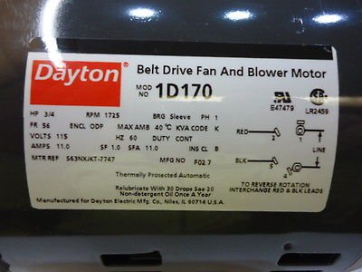
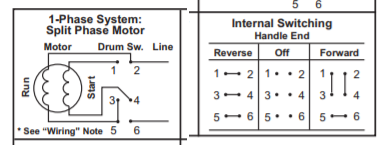
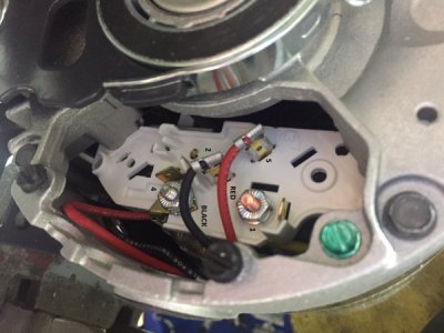
Thanks for your detailed reply, I think some of it went a bit over my head. I'll attach a couple of photos and hopefully this will help clear a few things up. I've labeled the terminals on the motor as they are marked, 1/4/2/5, as well as the red/black lines. On this switch I'll also attach a few images around it as well.

The 6 wires I have coming out of my motor are 1 for each terminal (1/2/4/5) and then a lead for both red and black. To reverse the motor, red/black need to swap across terminals 2/5 and I wasn't sure how to do this as shown in the image above (where they are hard-wired into the terminals).

IMG_0422.JPG

Dayton-Belt-Drive-Fan-Blower-Motor-3-4HP-_1.jpg

2601_switch.png
 
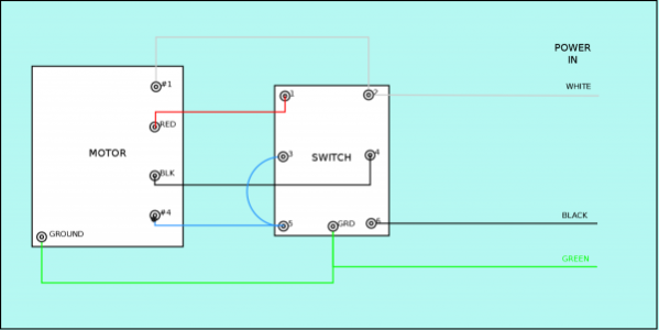
THIS IS WRONG! DON'T USE THIS DIAGRAM!


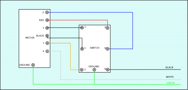
This should do it. Note the required jumper between pins #3 and #5 of switch. If motor direction is wrong for you swap red & black.

I believe the red and black should NOT be attached to the terminals in the motor. I think you only need 4 wires + ground (5 total) between the motor and the switch. I agree with Bill use matching crimp on connectors for the red & black.


SplitPhaseWireDiagram.png
 
Last edited:
So that looks like nothing should be connected to terminals 5 and 2? How then will the motor know which direction to spin without having the connecting point between the two?
 
Looks like clueless got it- try it out it should work
The red and black wires are the start leg
the terminals 2 and 5 are likely connected to 1 and 4 behind the terminal board, your drum switch will perform that function now
let us know if there is a problem- remember to let the motor come to a stop before reversing direction
mark
 
Last edited:
Looks like clueless got it- try it out it should work
The red and black wires are the start leg
the terminals 2 and 5 are likely connected to 1 and 4 behind the terminal board, your drum switch will perform that function now
let us know if there is a problem- remember to let the motor come to a stop before reversing direction
mark

Sounds good to me! I will give it a shot and see what happens. Thanks for the input.
 
WAIT! Don't use that diagram above, I think I made an incorrect assumption.

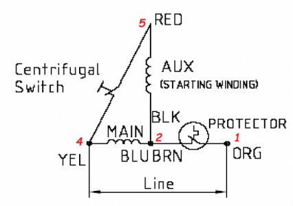
When I made that diagram I assumed that the start winding and centrifugal switch were in series between the red & black wires. That assumption appears NOT to be correct. I found the following diagram on the Grainger page that makes me think I was wrong.

https://www.grainger.com/ec/pdf/1D170_18.pdf

I need to think about this some more!
 
Last edited:
WAIT! Don't use that diagram, I think I made an incorrect assumption.

When I made that diagram I assumed that the start winding and centrifugal switch were in series between the red & black wires. That assumption appears NOT to be correct. I found the following diagram on the Grainger page that makes me think I was wrong.

https://www.grainger.com/ec/pdf/1D170_18.pdf

I need to think about this some more!

Alright, I'll let it be tonight until we can get this sorted.
 
All right, lets do this in steps. First off, to make the motor run, period. Leave everything connected by the photo. Take the line cord, (L1=black, L2=white) white to the stud on the motor. Either one, doesn't matter. Splice a wire onto the black wire and run to the switch. Connect the black, L1, to terminal S5 on the switch. Take another wire from terminal S6 back to the motor to the other stud. This is only to make the motor run. Direction is not relevant at this point. Flipping the switch in either direction will cause the motor to run.

Get this right first. Prove the motor is good and the belts are aligned and any other appropriate matter. All of this is working with the assumption there is a metal to metal conection from the frame of the motor to the frame of the switch. There must be a safety ground connection anywhere there is metal. This all ties back to the green wire of the line cord, usually at the motor, or at a terminal box if using one. It has always been my practice to use the extra wire and connect one wire to one terminal so anyone coming later can trace everything easily. Or more importantly, troubleshooting down the road after you have forgotten what was done. It only involves a couple of wires at this point, but makes things easier in the future. There is multi conductor cable available but if nothing else buy a roll of AWG14 white and lable each wire as you work. With THHN, a Sharpie will last long enough. Mark every wire.

Once all this is done, proving the motor &c, we want to make it run in reverse as well as forward. This is where you need another 4 wires. We want to reverse the connection of the start winding, relative to the rest of the motor. Looking at the photo of the motor, it appears that M5=Red and M2=Black. These two connections are the 1/4" staps. What wire goes where inside the motor doesn't matter to us. The manufacturer says to reverse these two to reverse the motor. That is the key phrase.

Refer to my earlier post, where the leads from the two stabs, M2 and M5, run to the switch, S1 and S4. S2 and S3 then run back to the motor, (M)Black and (M)Red. There should be no interconnection between the line, L1 and L2, and the reversing function at M2 and M5 or the (M)Red and (M)Black wires.

I must advise that there are "shortcuts" and wire count reduction methods. There are many possible ways to connect such a reversing switch. There are some involving speeds that even SqD doesn't show. What I've given here is a brute force simple connection for someone not too familiar with electricity. Most of my knowledge is "old school", almost useless in todays world. But old school work still exists with some things. My suggestion would be to assure you have at hand that universal lubricant first.(coffee) Then, and only then, try to figure this out.
 
Bill,

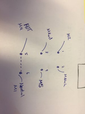
Thanks for the input. I drew out on a sheet what I believe you are suggesting. How does this not just connect hot and neutral from the outlet together and trip a breaker? The switch connects 5-6 always when either FWD or REV so this to me looks like it would just connect those two?

I can confirm the motor works, and I have been able to wire it both to run CW and CCW, this was hard wiring the motor and plugging into outlet, I then unplugged, flipped red and black leads, and plugged back in to get CCW rotation. So the motor does work as we expect.

IMG_0433.JPG
 
I think this is correct now. Note the neutral is not switched and connects directly to the motor.


Dayton1D170Corrected.png

The red numbers are my best guess at the motor internal connections, sure would be nice
if Grainger would actually give you that information!

Dayton1D170Cropped.png
 
Last edited:
Back
Top