-
Welcome back Guest! Did you know you can mentor other members here at H-M? If not, please check out our Relaunch of Hobby Machinist Mentoring Program!
You are using an out of date browser. It may not display this or other websites correctly.
You should upgrade or use an alternative browser.
You should upgrade or use an alternative browser.
Yet another large direct reading cross slide dial...
- Thread starter Dranreb
- Start date
- Joined
- Nov 18, 2012
- Messages
- 1,352
David, you could use a set screw or two. Put a piece of lead or brass under the screw if you wish to not mark the shaft.
Pierre
Yes Pierre and it looks like on Bernard's drawing that is what he is suggesting. My concern is that it won't hold very well, however not sure yet whether the set screw would land on the smooth shaft or the original threads.
Thank you for the suggestion.
David
- Joined
- Sep 20, 2012
- Messages
- 560
Bernard I took the handle off and looked at how stuff fits together. As you know the handle drives the shaft via a woodruff key, and the nuts on either side of the handle adjust the end play of the lead screw.
I am trying to figure out how to attach the extension so it will have a positive drive to the shaft as well as allow for adjustment of the end play. I really don't want to modify any original parts, and rather not use loctite. The shaft is only 5/16" with NF thread.
Any suggestions for locking the extension on?
Thank you
David
I showed flat with a grub screw at the end of the extension in my drawing, but in my mind there where two opposite flats to take a spanner, each with a grub screw to grab onto the smooth part of the shaft where the original dial sat, this would most likely be enough as some lathes drive pulleys are held on by no more than that.
But just thought of another maybe better belt and braces design, how about you drill and thread the whole extension piece right through, then,as your original shaft will not reach right through, the keyed part to hold the crank handle could be made from a separate piece of threaded rod.
If the crank was then fitted to this and it was screwed in until it jams against the end of your original shaft that would be your adjustment locking method. and lock everything up tight, then a nut on the end to hold the crank and it should be OK.
Tighten the grub screws last.
As Pierre says a bit of lead or brass will prevent spreading or damage.
I am waiting on a couple of small needle thrust washer sets to fit to mine, will post pics if it works out OK,
Bernard
Will be happy to draw what I'm suggesting but not right now gotta be elsewhere....
Last edited:
- Joined
- Nov 18, 2012
- Messages
- 1,352
Bernard, again thank you for your suggestions. Please don't do a drawing. I am working from the fixed pointer toward the handle in the part making process and sort of going to adapt and make as I go along. Just in the process of making the fixed pointer "dial" such that it can be located forward and clear the cross slide.
David
David
- Joined
- Sep 20, 2012
- Messages
- 560
David, great to know you're making parts...Just a quick thought, the grub screw holes in the flats would not have a lot of thread meaning short screws, they would be better if rotated 90 deg where there's more metal...
Bernard
Bernard
Last edited:
- Joined
- Feb 17, 2013
- Messages
- 314
Hi Bernard,
Nice job! Did you stamp the numbers by eye or did you use a guide?
Thanks,
Michael
Nice job! Did you stamp the numbers by eye or did you use a guide?
Thanks,
Michael
- Joined
- Sep 20, 2012
- Messages
- 560
Hi Bernard,
Nice job! Did you stamp the numbers by eye or did you use a guide?
Thanks,
Michael
Hi Micheal thanks, I stamped the numbers holding the punches in one of those old type tool holders fitted to my QCTP copied from another members method (sorry can't find the post now) I had a problem with a sloppy fit because my punches are metric. I'll mill a tight fitting guide out of ally for next time, just a slot to lay the punch in with a finger to hold it down should do.
This and the fact my chuck came loose due to me turning it backwards in order to see where the numbers where at, meant I had to turn it all off to start again which was what I meant by my comment:
'I hope y'all like the way I've stylishly turned down the numbered area, this detail took a while to achieve...:lmao: '
I had changed my chuck during the making of the parts and although I was just moving it slowly by hand and tapping very lightly it came loose and I took a while to notice..
Likewise when scribing the divisions using the dividing disc on my first attempt, at first I had the pointer above the center line as it was easier to see, don't know why but this induced an error somehow, it was OK at the center line no probs.
Bernard
- Joined
- Nov 18, 2012
- Messages
- 1,352
Bernard et al. I am about 80% finished my project. I sort of make a part then proceed to see what needs to happen next, rather than make a big set of plans then go for it.
How did you do the graduations? I am engraving them, but sure takes time.
Also I am using mainly 6061-T6 aluminum and brass, mainly because that is what I normally work with, and the little atlas is slow going with steel. I don't have any free machining steel....the L stuff.
If there is some interest I suppose I should start a new thread "the Little 618 with a BIG dial"?
Happy New Year
David
- Joined
- Jun 23, 2011
- Messages
- 120
I'd like to see that.
- Joined
- Sep 20, 2012
- Messages
- 560
Yes David, we do indeed think you should start another thread and that title just needs Atlas in it so folk can find it easily when searching...:thumbzup:
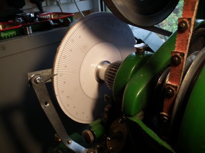
I used this method of indexing, the size difference eliminates errors very well, I posted a PDF of my numbered version earlier in this thread, you may have missed it.

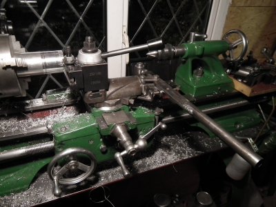
I cut the graduations using my lever compound (very quick) and a hooked cutter to curl the chips out better.
You could use the same type of tool in your locked compound, just by moving the carriage and using a carriage stop.
http://www.hobby-machinist.com/showthread.php/19267-Lever-operated-compound-top-slide

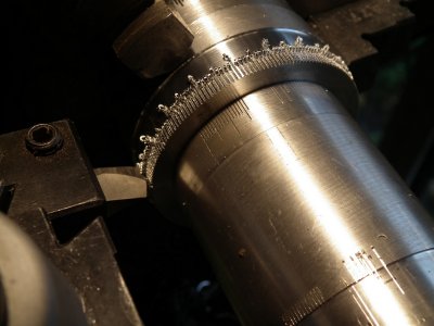
Cutting, practice cuts can be seen on the piece I used to put tailstock pressure on the workpiece to stop any chance of movement.

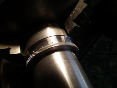
Turned off the chips

Happy new year
Bernard


I used this method of indexing, the size difference eliminates errors very well, I posted a PDF of my numbered version earlier in this thread, you may have missed it.

I cut the graduations using my lever compound (very quick) and a hooked cutter to curl the chips out better.
You could use the same type of tool in your locked compound, just by moving the carriage and using a carriage stop.
http://www.hobby-machinist.com/showthread.php/19267-Lever-operated-compound-top-slide

Cutting, practice cuts can be seen on the piece I used to put tailstock pressure on the workpiece to stop any chance of movement.

Turned off the chips

Happy new year
Bernard


