2015 POTD Thread Archive

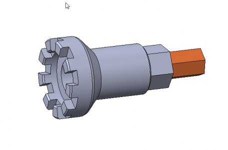
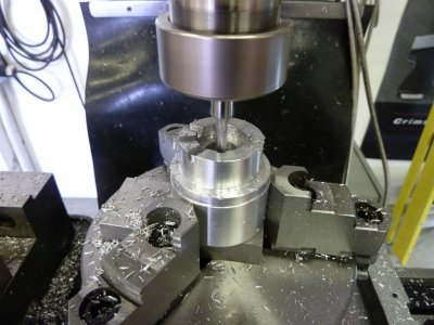
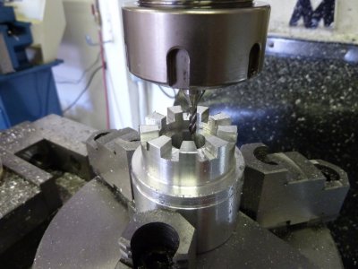
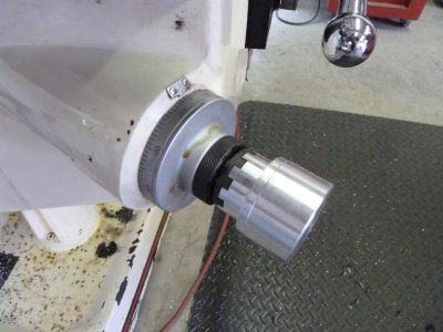
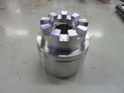
I made some progress today on a adapter to use a drill motor to power the knee. I saw this on one of Mr Pete's videos and thought this would be a great project as you use the lathe and mill with the rotary table. The piece I finished today is an aluminum proto to confirm the milling process and dimensions of the features that engage the knee crank. I used Mr Pete's dimensions and modeled it on SW. This SW screen shot shows the finished part. The hex drive will be pinned in place.
power knee adapter.jpg

power knee1.JPG

power knee2.JPG

power knee3.JPG

power knee4.JPG

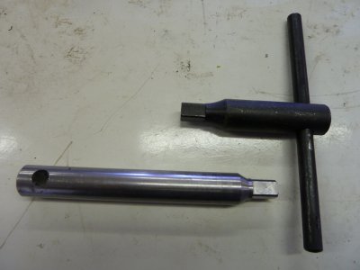
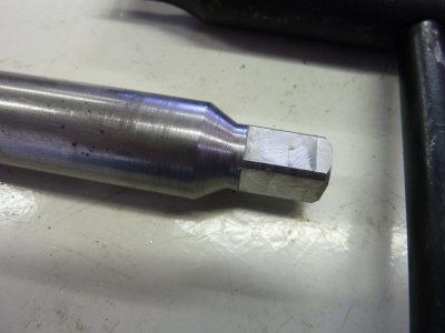
I'm also making a new chuck key for the rotary table as the one that came with it is too short. I was working on this while waiting on Enco for the end mills for the power knee project. Here is the main part mostly finished. I still need to make the cross bar and tig weld them together.
chuck key1.JPG

chuck key2.JPG
 
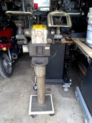
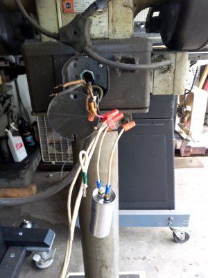
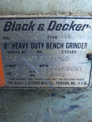
Won a Black & Decker 8" bench grinder at an auction. When I picked it up, I found that it was 3 phase. Did some research and found out how to connect a run capacitor across one of the motor windings, so it could run on 220 volt single phase power. Tested it and it worked great on the first try. The grinder runs so smooth, it takes 5 minuets & 23 seconds to come to a stop after the power was cut. Now, I'm going to completely clean it and re-wire it (except the motor windings).
I wouldn't do the capacitor trick with my milling machine (it already has VFDs for the motors), but the grinder will be used occasionally for cleaning burrs, so it will probably outlast me.

BD GRINDER1.jpg BD GRINDER2.jpg BD GRINDER3.jpg
 
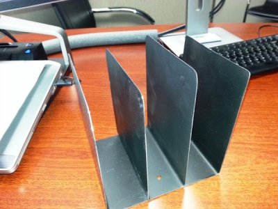
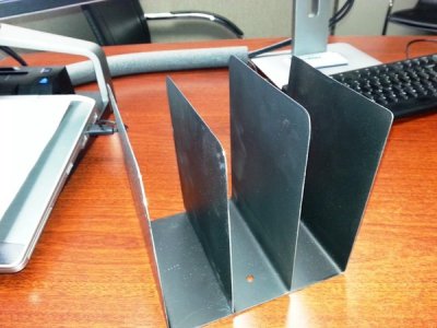
I have to make 40 pc of the following:
2995685b-b2d4-423c-9bf2-bed1f00af4da.jpg

Material is 20ga sheet steel.
Cut out the blanks a couple of nights ago. Belt sanded the corners and tonight set up to deburr the edges.

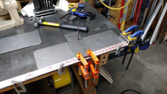
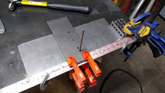
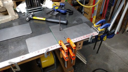
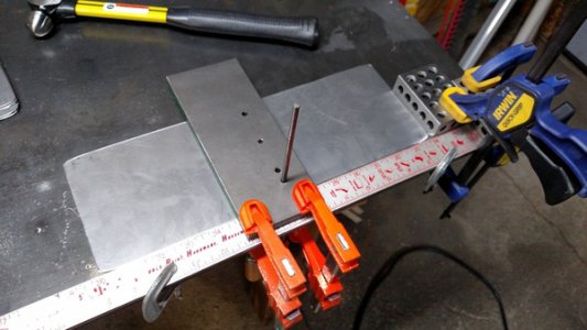
Set up a fixture to lay out the holes:
IMG_20150828_202630331.jpg
IMG_20150828_202820709.jpg

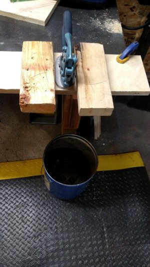
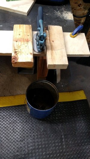
And then Punched the hole using a Roper Whitney no 5jr punch:

IMG_20150828_205123142.jpg

I am going to try to Paint them before I bend them. That is the project for tomorrow.


Jason

2995685b-b2d4-423c-9bf2-bed1f00af4da.jpg

IMG_20150828_202630331.jpg

IMG_20150828_202820709.jpg

IMG_20150828_205123142.jpg
 
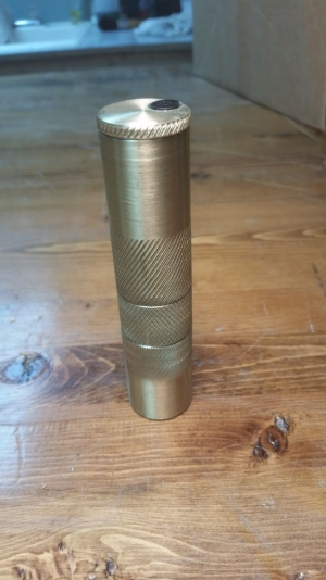
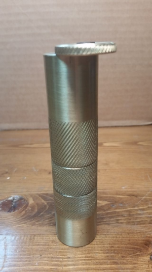
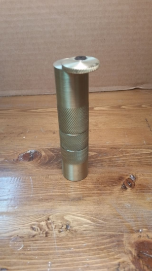
Found some Solid 1" Brass Rounds and decided to make a tool bit Center height gauge for the lathe.
Made it from watching Tom on Oxtools modify the Hardinge one he had.
Need to get a better knurling tool. One with smaller wheels.

upload_2015-8-28_23-32-39.png

upload_2015-8-28_23-32-51.png
upload_2015-8-28_23-33-1.png
 
Roadie, nice job.
I don't think the wheels are the issue rather setup, be sure that the wheels are perfectly on center. The tool pressure can cause the single line. You can try rotating the compound ever so slightly towards the tailstock to make up for the pressure. Also, what I do when I can, touch the wheels to the work, note the crossfeed dial reading, back off and move the carriage towards the tailstock, set your power feed up, and set rpms around 300-500, advance the cross a few thou and go for it. Doing it like this has netted me the nest results knurling. Made me go from "this knurling tool is a piece of crap" to "so that's how you do it" lol
I usually stop the machine, put in reverse FEED (motor ccw/standard)and let it back out off the work, stop the machine, forward FEED, advance another thou or so repeat until your happy. It works for me
 
Last edited:
Brino & All,
I can't find any information about the age of my bench grinder from Google or VintageMachine.com. Maybe there is someone around here that can look at the machine tag and enlighten us. Thanks for the likes & kind words.
 
Back
Top