2015 POTD Thread Archive

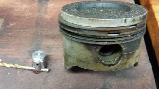
I'm making a keychain doodad for my brother. He's a heavy diesel mechanic.

I figure a piston & connecting rod will be a nice keychain doodad.

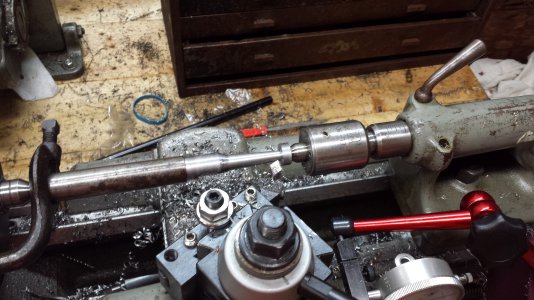
THIS IS A WATCH YOUR FINGERS PROJECT! It's too dang close to the lathe dog, and I am very, very careful when advancing the compound.

Tiny piston...


20150830_184529.jpg

Making a connecting rod:
20150830_201400.jpg
 
Sound kind of reminds me of the old "Johnny Popper" on the Farm. :D

I don't recall hearing Deere called that but my Dad grew up with them. We would go to tractor shows years ago
he would say hear that engine. Every time you think she died out of somewhere she would get enough energy to take off again. Those were the days
 
Quick little job tonight while waiting for a guy to come by the shop and pickup my OBA system that I posted up for sale last night.

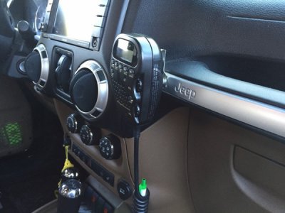
This part broke last week while my wife and I were in Ouray, CO wheeling. Can you guess what it is???

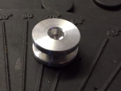
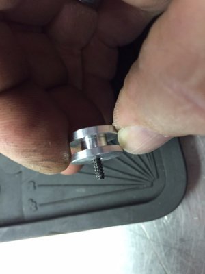
Started with a piece of .625" 6061 aluminum.
1z3q6nr.jpg

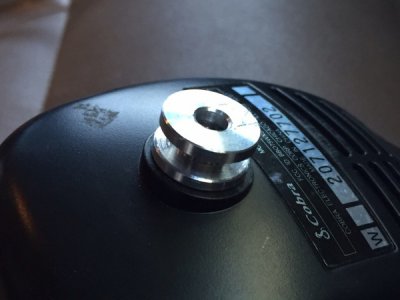
Part completed and ready for installation.
3452djc.jpg

2my0nxv.jpg

2lmwa3t.jpg

Any ideas yet????
2db41m0.jpg

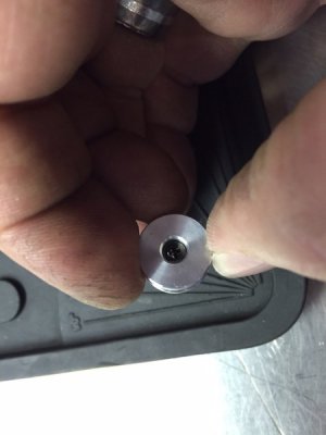
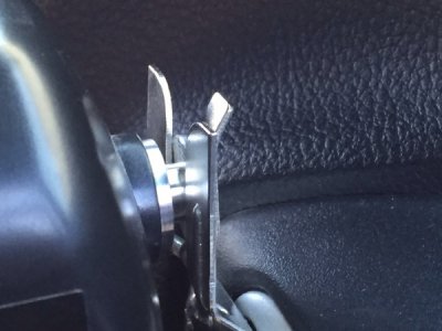
Last week the little plastic tab on the back of my CB mike broke. The cheap plastic tab was replaced with an aluminum one and she's done!!
qpj5th.jpg

fn9us6.jpg

Quick little 5 minute job that adds the "kool" factor.

Mike.
I like the pin in the coil. Must be a Ham radio operator. Nice project.

1z3q6nr.jpg

3452djc.jpg

2my0nxv.jpg

2lmwa3t.jpg

2db41m0.jpg

qpj5th.jpg

fn9us6.jpg
 
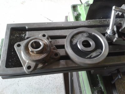
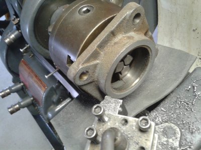
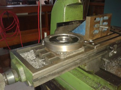
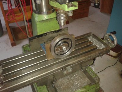
Started working on a rotary jig - Harold Hall's manual rotary table made me realise that I dont necessarily need a wormscrew/wormwheel - I haven't yet got the skill to make those.

http://www.projectsinmetal.com/a-simple-rotary-table-without-a-worm-drive/

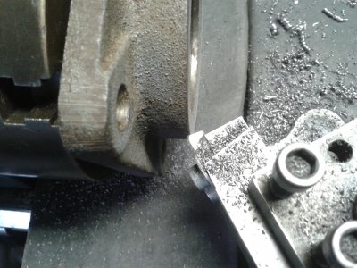
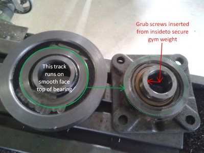
Haven't got a lump of cast iron 30mm thick - but I think I can improvise with my gym weights and a spherical bearing housing.

I need this table to help cut slots in my other project - the faceplate from gym weight.

Photos tell the story - should be finished tomorrow.

Suspect that if I stop and think for a bit I might get a better result but it is enjoyable simply to have a go and see what happens next.

Bill

1 Two components.jpg 2 Smooth face.jpg 3 Tangential worked well.jpg 4 Matched Faces.jpg 5 Weight Mounted.jpg 6 Drill for handle.jpg
 
I like the idea of using a gym weight. Always looking for good ideas of readily available items the can be easily repurposed.
I used an angle grinder to cut my table out of plate steel and it took a hell of a time to make it round in the lathe afterwards.
 
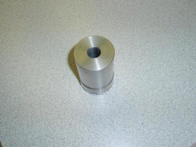
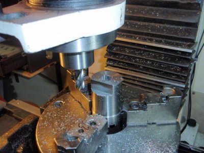
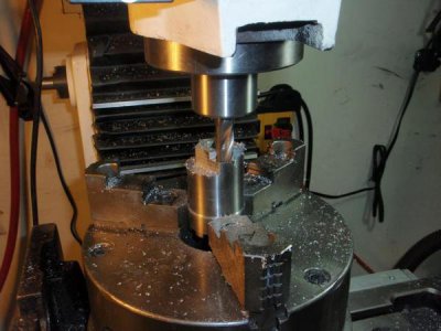
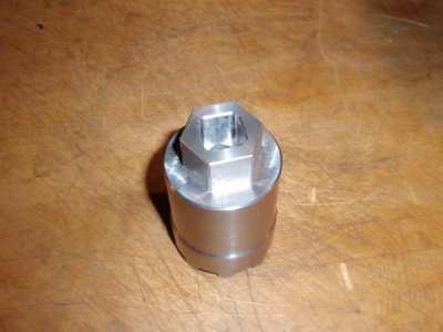
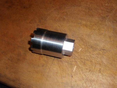
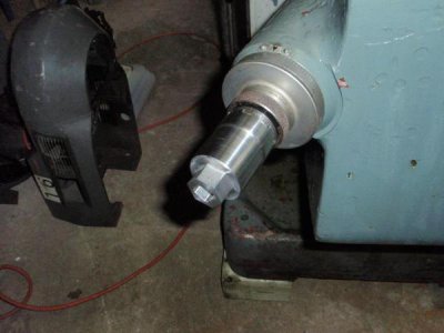
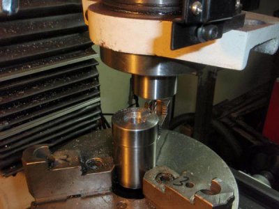
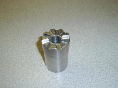
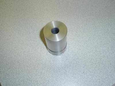
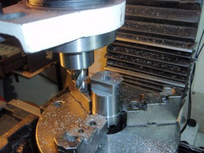
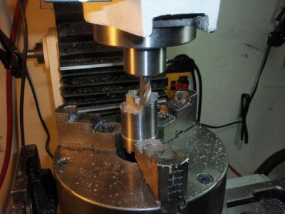
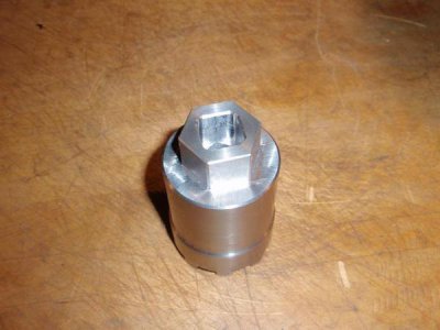
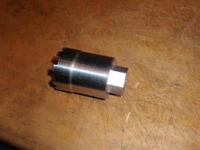
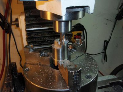
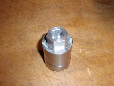
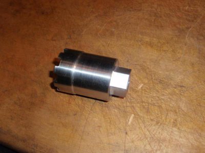
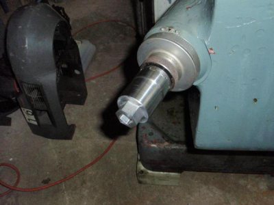
Continuing with the power knee chuck. Got the blank started by facing each end and turning one end to finished dimension. A 5/8" clearance hole and 1" counter bore was added to the end of the part. It was setup in the rotary table and the pins cut in three passes. When I checked it for fit on the knee crank I decided that I made the clearance hole too big. The clearance hole on my aluminum proto piece was .630" but the steel part was made to print at .650". I liked the fit of the proto piece so I made a second part. I ended up at .628" which fits snug which I like better. Next up is to remove some of the bulk to the main body and cut the 3/4" hex flats.
View attachment 109647
View attachment 109652
View attachment 109648
View attachment 109651
View attachment 109650
Hello there Sanddan
Nice work U doing there.
In the earlier "proto", nor here, U do not mention the actual Angle of Cut used to get the PINS to match. Am eager to know for future intended projects.
Do take pics of Your milling the HEX Part - keen to see how U do that as well.
In the pics we see U have copy of a drawing in the background, matter of interest, where'd U get Your Plans from - if it's not Copyright info as well ??
Take care and
TIA
aRM

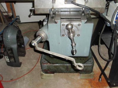
I made a similar one when I first bought my mill.

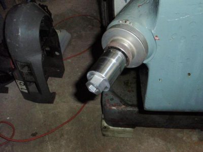
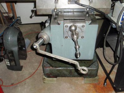
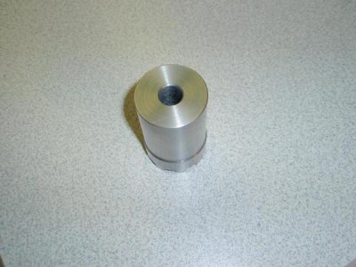
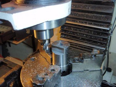
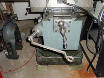
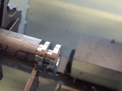
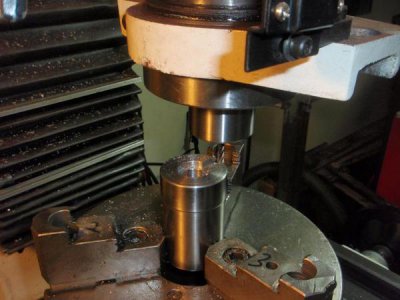
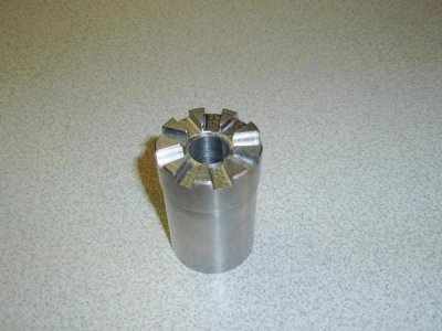
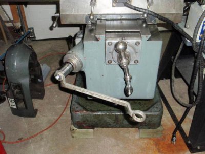
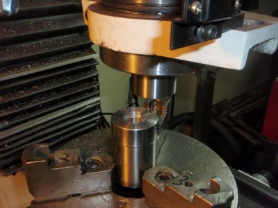
This mill did not come with a handle for raising/lowering the knee. I have a length of 1.75" stainless round stock so I used a 2" long piece to machine an adapter for the knee drive splines. It is a 9 spline drive with a 1.675" od. I used a 3/16" end mill and my super spacer on my PM932 mill to machine the spline and a 15/16" hex on the other end as well as a 1/2" square drive hole to use with a drill. I started by drilling a 1/2" hole all the way through and turning the entire length down to 1&5/8". Then I bored it to 5/8" part way to fit onto the knee. Then I milled the splines with 40 degree spacing with a 3/16" end mill. I found that if I milled out 4 degrees on each side of each 40 degree interval it gave the correct dimension spline to fit the machine.
P2090659_zpsa8f6aef5.jpg

P2130670_zps986d4502.jpg

P2130672_zps388bd902.jpg

P2130731_zps846d317c.jpg

P2130733_zpscf342d0b.jpg

P2130734_zpsdf96d6e0.jpg

P2130735_zps32702a1e.jpg

P2140739_zpsf51fb2b3.jpg

P2140740_zpsd391a6c7.jpg

P2090659_zpsa8f6aef5.jpg

P2130670_zps986d4502.jpg

P2130672_zps388bd902.jpg

P2130731_zps846d317c.jpg

P2130733_zpscf342d0b.jpg

P2130734_zpsdf96d6e0.jpg

P2130735_zps32702a1e.jpg

P2140739_zpsf51fb2b3.jpg

P2140740_zpsd391a6c7.jpg
 
I made a similar one when I first bought my mill.

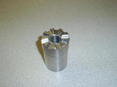
This mill did not come with a handle for raising/lowering the knee. I have a length of 1.75" stainless round stock so I used a 2" long piece to machine an adapter for the knee drive splines. It is a 9 spline drive with a 1.675" od. I used a 3/16" end mill and my super spacer on my PM932 mill to machine the spline and a 15/16" hex on the other end as well as a 1/2" square drive hole to use with a drill. I started by drilling a 1/2" hole all the way through and turning the entire length down to 1&5/8". Then I bored it to 5/8" part way to fit onto the knee. Then I milled the splines with 40 degree spacing with a 3/16" end mill. I found that if I milled out 4 degrees on each side of each 40 degree interval it gave the correct dimension spline to fit the machine.
P2090659_zpsa8f6aef5.jpg

P2130670_zps986d4502.jpg

P2130672_zps388bd902.jpg

P2130731_zps846d317c.jpg

P2130733_zpscf342d0b.jpg

P2130734_zpsdf96d6e0.jpg

P2130735_zps32702a1e.jpg

P2140739_zpsf51fb2b3.jpg

P2140740_zpsd391a6c7.jpg
Hi JohnnyC
Very well related
Thanks a stack
Take Care
aRM

P2090659_zpsa8f6aef5.jpg

P2130670_zps986d4502.jpg

P2130672_zps388bd902.jpg

P2130731_zps846d317c.jpg

P2130733_zpscf342d0b.jpg

P2130734_zpsdf96d6e0.jpg

P2130735_zps32702a1e.jpg

P2140739_zpsf51fb2b3.jpg

P2140740_zpsd391a6c7.jpg
 
Back
Top