2014 POTD Thread Archive

Re: POTD - I Did This.

I worked on this today...the entire day..

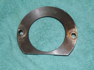
I made this;
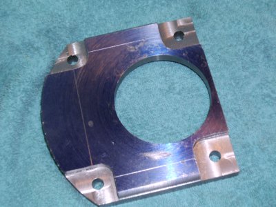
SANY0017.JPG

It replaces this;

SANY0018.JPG


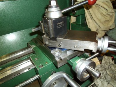
And it goes here;

SANY0019.JPG

It's the compound support/mount. I've made it with four holes, based on a design I saw somewhere, perhaps on this site. It makes it easier to access and tighten the bolts and may give a little more stability.

Made it from 12L14, mild steel, lost a nut or two during clean up, probably thrown out with the pile of chips I generated machining this.

Still have some finishing to do on it. Deburring, sanding and stoning.

SANY0017.JPG SANY0018.JPG SANY0019.JPG
 
Re: POTD - I Did This.

View attachment 83291

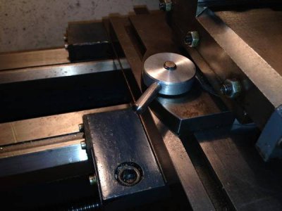
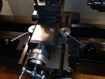
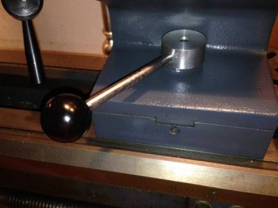
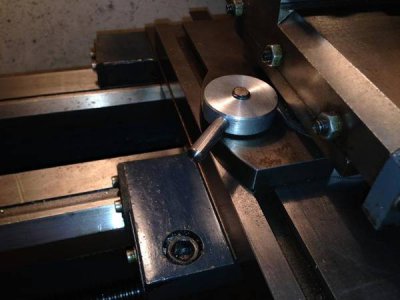
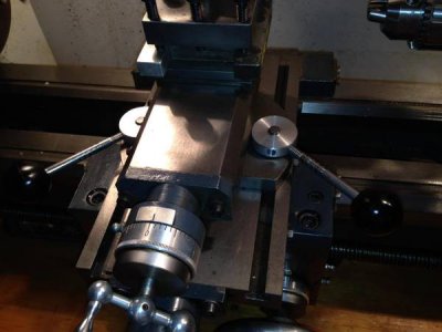
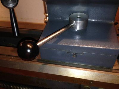
Here is something that might make it even better. On my lathe I was tired of getting out a wrench every time I wanted to move the fixture around so made these easy to move levers just like nuts and easily tightened down. Mine needed to be that shape to be low and let me thread in the handle. I made them that way also to allow me to tighten most of the way with no handle then mark and drill and tap the handle location. Yours could be similar but to fit your space. Then you just reach down, lever, level lever, lever. Move the holder and tighten back down instead of getting a wrench on there.

I have a set of longer handles with balls on the end when they wouldn't be in the way like almost all the time. You would use longer ones out back. I used stainless steel 6 inch bolts for the handles because they are strong and one end already threaded

photo-7.jpg

photo-5.jpg

And the tail stock

photo-4.jpg

photo-7.jpg

photo-5.jpg

photo-4.jpg
 
Last edited:
Milled off 1/8" from a die for a fly press for a friend.

Bigger job is repairing the rack screw for another friend's belt drive 12 x 36" Grizzly lathe. This lathe has broken down a few times,and now no parts available.

The rack gear dubbed over teeth,and the rack got teeth broken off. Nothing was hardened.

I will tell you that this lathe's rack is TOO SMALL for a lathe this size,and too weak. It is only about 1/2" square. I can only mill off the bad teeth,leaving barely enough room for the new teeth to engage the rack. Adding collars to re position the rack gear,which is about 1" wide,but needs less than 1/2" to engage the rack. After this last bit wears out,he's screwed.except for cutting a whole new gear and shaft.

I have told him to turn the rack around. The carriage will not be able to engage the broken part of the rack. I think he'd better be gentle with the new setup. And,to think I might have wanted one of those belt drive lathes from Grizzly(now discontinued). Never had any problem with my old Taiwan made 10x24" Jet. No trouble with my 1986 Grizzly Taiwan made 16" lathe. But,that lathe is Taiwan made.

Told him to get a PM lathe made in Taiwan next time. He's thinking of taking the carriage off and just using the lathe for a polishing lathe for gun barrels. Some time ago,when parts COULD be had,it took him about 2 years for Grizzly to cough them up. Luckily,he has another lathe. The trouble that time was screwed up gears in the QC box. Better spend your money on a Taiwan made lathe.
 
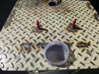
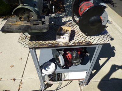
Old grinder stand was HF junk, very flimsy.

This enco stand can support up to 1500 lbs.

center of table 3 inch hole for power cords


red pins, swap out 8 inch red grinders, quickly


tool grinder is permanetly mounted


3 shelves


Charl

P1010123.JPGP1010128.JPG

P1010123.JPG P1010128.JPG
 
I made a tool holder holder.

[video=youtube_share;n7TqjQ8AoCI]http://youtu.be/n7TqjQ8AoCI[/video]

Nicely done, sort of a modified french cleat. I really like the fast forward, lets one see the process in 1/10th(or less) the time.

Brian
 
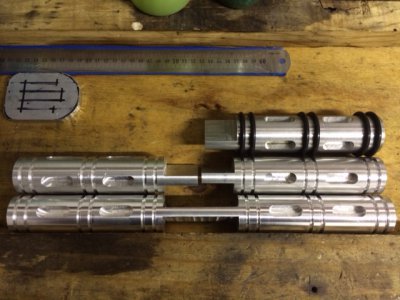
Motorcycle foot pegs

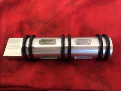
A friend wanted to make some large foot peg for his motorcycle so he came around and we spent the day together making them up.

After machining up one peg as a prototype we set about machining two further sets as a mirrored pair per bar.
photo.JPG
photo2.JPG

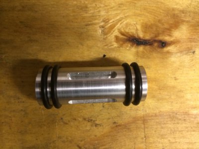
End Result
photo4.JPG

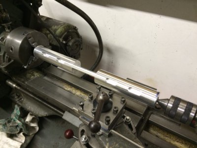
We did all the mill work first (other that facing the ends of the stock on the lathe), indexing 4 flats on the bars then milling the all the outer slots using stops, resetting and milling all the inner slots. Then milled the tang in the middle (which may has been a mistake).

Then transferred them to the lathe and turned them down to round again - removing the indexing flats, and cut the slots with a parting tool. The four slots nearest the centre were a bit of a problem a with the middle of the bar already milled out it was stiff in one axis but flexed in the other. I haven't measured but I guess those slots are pretty oval but that is not really a concern.

Then knocked up a matching gear shift end go with them.
photo3.JPG

Still to do the brake pedal some time this week and then the plan is to have a try at anodising them next weekend.

photo.JPG photo2.JPG photo3.JPG photo4.JPG
 
Nicely done, sort of a modified french cleat. I really like the fast forward, lets one see the process in 1/10th(or less) the time.

Brian

Thanks Brian, I am trying to do lots of fast forward on my vids since I'm not really trying to educate someone on how to do something so I think it should be a fun couple minutes of time to view.
 
Motorcycle foot pegs

A friend wanted to make some large foot peg for his motorcycle so he came around and we spent the day together making them up.

After machining up one peg as a prototype we set about machining two further sets as a mirrored pair per bar.
View attachment 83331
View attachment 83332

End Result
View attachment 83334

We did all the mill work first (other that facing the ends of the stock on the lathe), indexing 4 flats on the bars then milling the all the outer slots using stops, resetting and milling all the inner slots. Then milled the tang in the middle (which may has been a mistake).

Then transferred them to the lathe and turned them down to round again - removing the indexing flats, and cut the slots with a parting tool. The four slots nearest the centre were a bit of a problem a with the middle of the bar already milled out it was stiff in one axis but flexed in the other. I haven't measured but I guess those slots are pretty oval but that is not really a concern.

Then knocked up a matching gear shift end go with them.
View attachment 83333

Still to do the brake pedal some time this week and then the plan is to have a try at anodising them next weekend.

I have seen the O-rings on them before but was wondering why? Is it just for cushioning? Do they last very long?
 
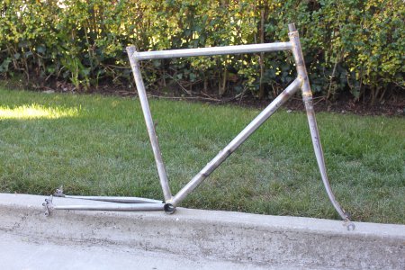
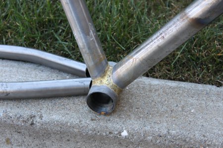
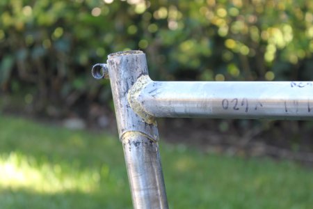
I spent some time this weekend making a fillet-brazed bike for a friend. The fork needs shortening and the chain stays aren't attached yet, but it's getting there.
2014_09_07_4406.JPG
2014_09_07_4407.JPG
2014_09_07_4408.JPG

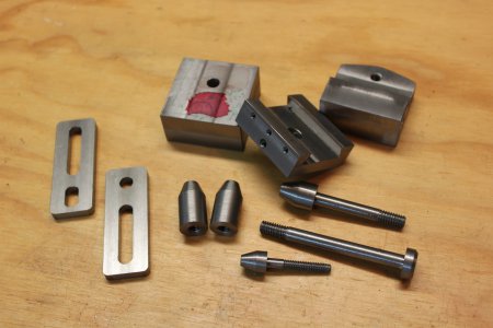
I also got a few more pieces of my Harold Hall Grinder Rest done. Full thread to follow when it's done.
2014_09_07_4417.JPG

-Ryan

2014_09_07_4406.JPG 2014_09_07_4407.JPG 2014_09_07_4408.JPG 2014_09_07_4417.JPG
 
I have seen the O-rings on them before but was wondering why? Is it just for cushioning? Do they last very long?

My feeling is more for a bit of traction. The smooth aluminium would get quite slippery in the wet.
The other alternative I have seem is leaving a couple of knurled ridges - but we decided to go with the O-rings.
 
Back
Top