2014 POTD Thread Archive

Wow that is really neat! To me that is the epitome of learning and having a home machine shop; you never stuck for a tool or part...just build it yourself!

Hopefully one day I will have mastered the sufficient skills.....:))

Machined an adapter plate for a friends project car, this allows one to use a Volvo front wheel drive 5 cylinder or 6 cylinder engine and mate it to a Ford T5 transmission to be installed in a rear wheel drive car.

Thought it was going to be a one-off, now a few more Volvo fans want one...
 
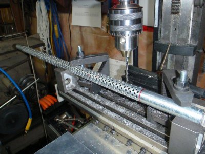
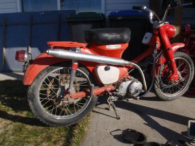
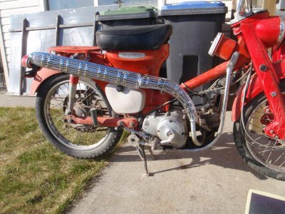
I had to drill 986 holes last year when I made a new exhaust system and muffler for my 1965 Honda trail bike. I didn't have the fourth axis set up for the CNC, so I rotated the pipe manually for each row. It sure was easier to do with a little help from the computer. Steve's method is even better.
P3230861a.jpg

P3230863a.jpg

P3240865a.jpg

P3230861a.jpg P3230863a.jpg P3240865a.jpg
 
Nice work, I don't think a cake could be so heavy to require tapered roller bearings!

P.S.: We would be glad to see some cake photos, too :)

Thanks! They're actually standard ball bearings though, I'm fitting a thrust bearing to take the vertical loading. This thing is never going to break.

carlos,

For aligning a center point in a 4-jaw chuck I made a "wobbler". Not my invention...several on Google Images. I added the small scale in the talestock chuck to give me a reference on my adjustments.

Ken

The Wobbler was actually what inspired the build, I was wanting to make one but found I didn't really have the parts and tools to do it how I liked so I made the pin instead. Yours looks very nice indeed.


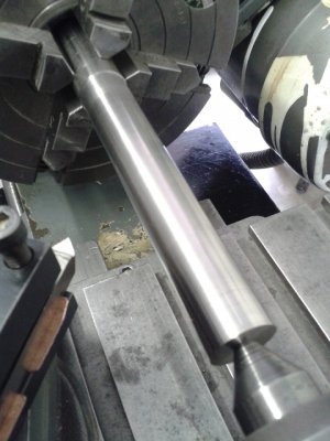
My friend and I have started building the parts for our 5'' steam locomotive. I'm teaching him some basic machining and we're having a great time. We started with the axles, using stainless steel because the BMS I had was much greater in diameter. Seen in the picture is one of the axles partially machined, using a pointed tool set so that the cutting edge 'rubs', for fine surface finish.
20140518_102026.jpg

20140518_102026.jpg
 
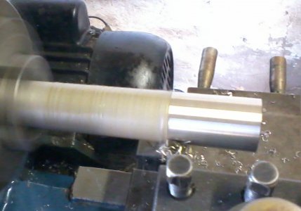
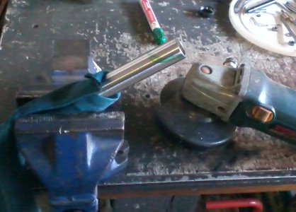
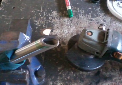
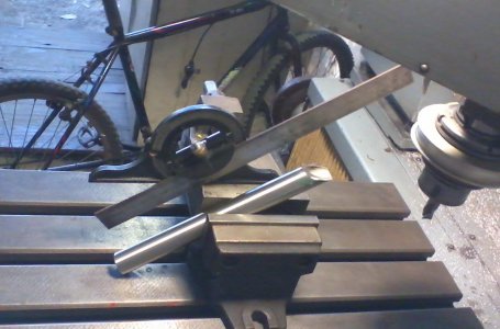
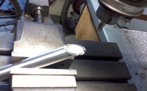
Needed a custom (longer than standard) tube for my bicycles custom handle bars.

01-turn-down-tube.jpg
Scrounged some tube that was near size and turned it down a little.
02-setup-for-angle-grind.jpg
Roughing procedure setup.
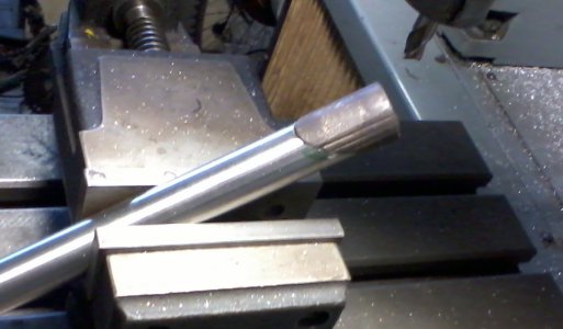
03-angle-grind.jpg
All roughed up.
04-set-for-mill.jpg
Eyeballing the angle will do here.
05-pantograph-mill.jpg
Yea ole pantograph mill.
06-mating-part-check.jpg
Mating part.

Now I need to scrounge material for an adapter sleeve to make it fit at the neck.

01-turn-down-tube.jpg 02-setup-for-angle-grind.jpg 03-angle-grind.jpg 04-set-for-mill.jpg 05-pantograph-mill.jpg 06-mating-part-check.jpg
 
After I bought my "Barbie Sunday Woodworker Bandsaw" I watched many videos to learn how it works etc.
In a video I noticed a strange jig keeping the wood pressed against the fence: a neat idea, able to save some fingers.
A search brought me to the Rockler site: this jig is called "Rockler Thin Rip Tablesaw Jig" - http://www.rockler.com/thin-rip-tablesaw-jig
Of course, since the table of my bandsaw is made with coffee can tinfoil and not with a cast iron slab with good guides, I had to invent something else, even because $19.99+shipping for such a jig seems to me a bit excessive.
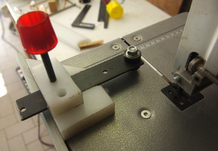
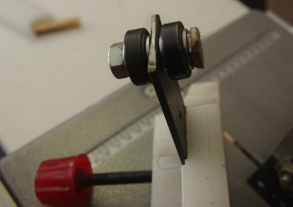
So I got a couple of 608ZZ ball bearings (those for skates), an M8 bolt, a piece of iron, a couple of scraps of my usual plastic and the handle of a broken Chinese pipe cutter.
A scrap of aluminum profile became the "guide" of my tinfoil table.
Here is the result:

rip_jig_1.jpg

rip_jig_2.jpg

The head of the bolt is cut to leave just a support for the bearing, and I placed one of those adhesive felts used for the chairs feet below it to avoid to scratch my precious table.
The iron bar slides inside a dado cut in the plastic with a wood router bit.
I still have to round a bit all the corners, but the jig works smoothly (actually better than the bandsaw itself!).

rip_jig_1.jpg rip_jig_2.jpg
 
I had to drill 986 holes last year when I made a new exhaust system and muffler for my 1965 Honda trail bike. I didn't have the fourth axis set up for the CNC, so I rotated the pipe manually for each row. It sure was easier to do with a little help from the computer. Steve's method is even better.

View attachment 77140

Nice old bike. Is it a restoration project?

A couple of months back I needed to champher 1080 (10mm) holes in a granulator grid plate. Thankfully I had a CNC to help me with that too.

- - - Updated - - -


Handy tool to have Marco, I must try and remember this. What is the red plastic, some sort of cap?
 
Handy tool to have Marco, I must try and remember this. What is the red plastic, some sort of cap?

Thanks!
The red plastic is the handle of a pipe cutter I broke, with an M8 thread bar.
Probably if I'd have to buy it alone it would be more expensive than the whole pipe cutter :lmao:
 
The bike is something I wanted back when they were new. A friend had it kicking around and I bought it from him. I'm slowly fixing it up as a rider. I made a rack for the back of my car to carry it up into the hills.

The big sprocket is for off-road speeds up to 20 mph. It is mounted over a smaller sprocket that allows road speeds. I doubt I'll ever use the small sprocket.I have three better bikes for highway use.

The next model featured a high/low range shifter for easier mode changing.
 
Okay, finally finished up my new bench grinder pedestal and downloaded the camera.


I purchased a package of four high durometer rubber/poly feet from the hardware store and made three corner mounted plates for the underside of the base. These were drilled and tapped for a 10-32 screw through the center of the poly foot. I recessed the drilled/tapped plate up under just far enough to allow only about a 3/16" of the foot to protrude below the base. This will keep metal shaving and debris from gathering under the base.


Here is the poly foot attached to the drilled/tapped plate under the base.
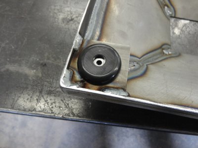
28c29lj.jpg


Here you can see roughly how far below the bottom of the base the poly foot protrudes.
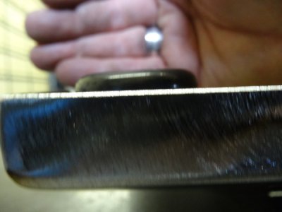
21bu82f.jpg


The fourth foot I mounted on a 10" piece of 1/8"x2" wide strap that is welded to the opposite corner of the base. The poly foot is then screwed to the end that is not welded to the base. I fabricated a 1/4" thick piece of steel that is drilled/tapped for a 3/8"-24 set screw that can be adjusted to retract or extend that fourth foot for final adjustment. I drilled a hole through the top of the base in which an allen wrench/T-handle can be inserted and adjust the level of the stand.


Here is the fourth poly foot screwed to the steel strap.
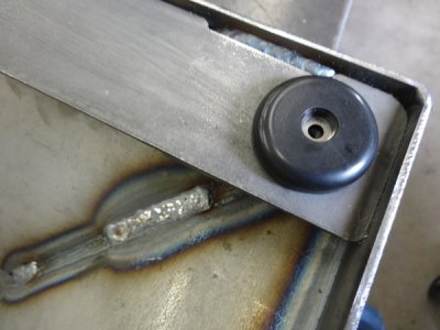
b7dz13.jpg


Here is the small opening for the allen wrench for the adjustment.
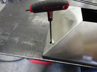
34zyijq.jpg


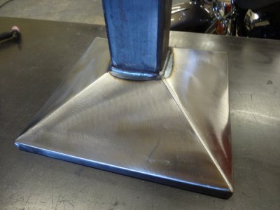
Here is the 3.5" square tube fit and welded into the base.
95zmgz.jpg


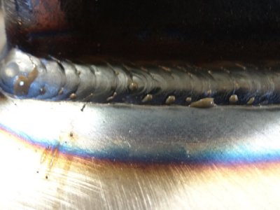
Closeup of one of my welds on the base to column.
2aglr83.jpg


Prior to paint I decided to add a small tray to place drill bits or lathe tools on when grinding. I was going to add a small water tray but I have a water container mounted on the disc/belt sander right next to this that I figured I would use rather than have two pieces of equipment with water trays attached.


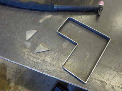
Here is the frame for the small parts/tool tray. I bent some 1/2" wide .125" thick steel to the shape that I wanted. I also added two triangular mounting tabs which will be used to secure the tray to the column. I didn't want to weld it on so I made it attach by two button head socket machine screws drilled/tapped into the column. After getting the frame bent I placed it on some 12-gauge P&O and traced it, cut it on the vertical bandsaw and TIG welded it together. I then metal finished it and prepped everything for a coat of machinery gray paint.
5yw50w.jpg


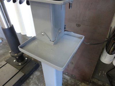
Here is the tray along with the stainless steel button head socket head screws attaching it to the column.
2poe6b9.jpg


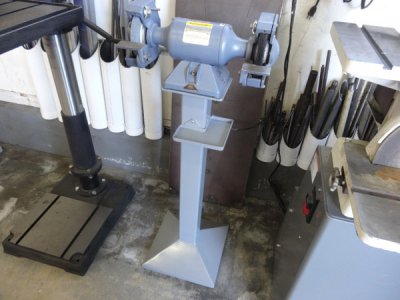
Completed with the Baldor grinder bolted on and ready to use. It looks right at home between the Jet drill press and Wilton disc/belt sander. It looks like it has belonged there all along.
2wel3yq.jpg


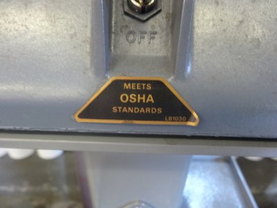
And of course, last but not least the sticker that gives me the warm and fuzzies because without this it would probably kill me if I used it.
30j1wzs.jpg


I wish I could take complete credit for the design but I cannot. I stumbled across it on the internet a few months ago and thought to myself that I liked the design. You know what they say, imitation is the the most sincere form of flattery. However, I will be damned if I can remember where I saw it at. I was flipping through machining images on Google and stumbled across it somewhere. I just added my personal touch to it.


Mike.
 
Back
Top