-
Welcome back Guest! Did you know you can mentor other members here at H-M? If not, please check out our Relaunch of Hobby Machinist Mentoring Program!
- Forums
- THE PROJECTS AREA
- PROJECT OF THE DAY --- WHAT DID YOU DO IN YOUR SHOP TODAY?
- Project of the Day Mega-Thread Archives
You are using an out of date browser. It may not display this or other websites correctly.
You should upgrade or use an alternative browser.
You should upgrade or use an alternative browser.
2015 POTD Thread Archive
- Thread starter jumps4
- Start date
- Joined
- Jun 14, 2014
- Messages
- 410
Two projects to speak of today:
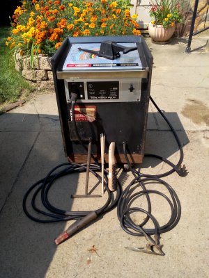
1. Cleaned up and repaired a 1968 Craftsman welder to re-sell. I was really glad that the escutcheon was covered up with the clear coat laminate for 47 years. Took awhile to remove, but underneath was a diamond in the rough. See first picture.
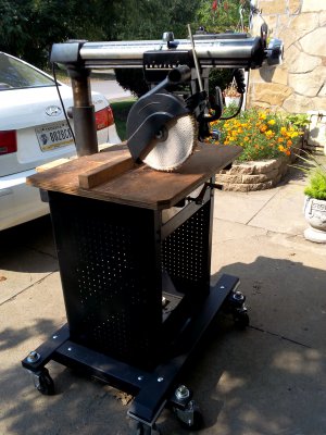
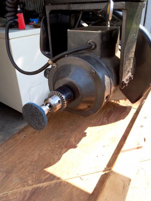
2. Set up my 1968 Craftsman 100 radial arm saw (RAS) for buffing & polishing. See second & third picture. Occasionally I use the RAS for compound miter and straight cross cuts. The cutting accuracy is enough for my needs, after tramming the head. However, I don't need to cut wood as often as I need to polish metal details. So I ordered a couple of 10" polishing wheels to mount together on the main arbor, and installed a drill chuck on the back end of the motor to hold a Scotch-Brite pad. I will advise anyone who wants to do this to spend the extra money and buy a high quality buffing pad. I regret buying a cheapies.


- Joined
- Jan 22, 2012
- Messages
- 655
Hello there Sanddan
Nice work U doing there.
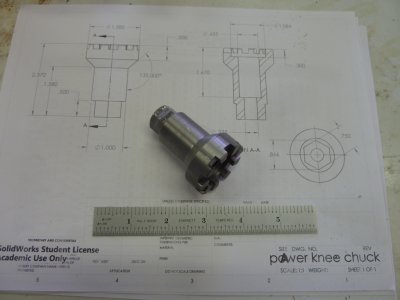
In the earlier "proto", nor here, U do not mention the actual Angle of Cut used to get the PINS to match. Am eager to know for future intended projects.
Do take pics of Your milling the HEX Part - keen to see how U do that as well.
In the pics we see U have copy of a drawing in the background, matter of interest, where'd U get Your Plans from - if it's not Copyright info as well ??
Take care and
TIA
aRM
MrPete222 on youtube does a 2 part video on making this adapter. As stated earlier, the pins are 40 deg apart. The pins are formed in three passes on the rotary table. First pass is done with a 3/16" end mill which gives you a straight pin. To get the 20 deg taper you make 2 passes using a 1/8" endmill. 1st pass the table is shifted .060" in x direction and the rotary table is turned 10 deg, this makes a tapered cut on one side of each pin. For the third pass the table is shifted .060" the neg direction and the table rotated 10 deg in the opposite direction to cut the other side of the pin. The result is a pin tapered to 20 deg. I turned the main body down to 1" and left 1" of extra material so I could mount it in a hex block with a 1" collet. I cut the 3/4" hex with a 1/2" end mill, sorry I didn't take any pictures of that part, and cut the excess material of with the bandsaw. I chucked it in the lathe and faced the end and drilled a 3/8" hole for the 1/2 hex bar that's still to be made.
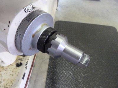
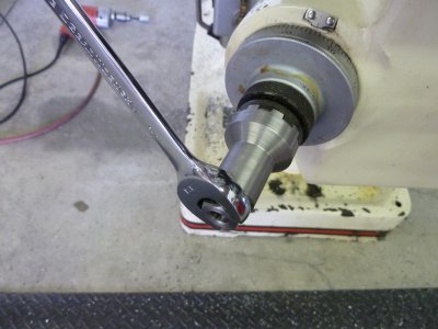
I finished the main body of the adapter and it does work but it takes a lot of torque to raise the knee. A 3/8" cordless drill stalled out and my 1/2" hole shooter would do it but you better hang on with 2 hands. I have a 49" table so maybe it's just the extra weight. I also had my 6" vise and 8" rotary table with 6" chuck all mounted on the table so extra weight there. I've never used another knee mill so not sure if this is normal or not but this is how mine is. I will attach a link to the video series and a PDF file of the drawing.
power knee chuck.PDF
Attachments
Last edited:
Thanks a zillion for taking time to respond SANDDAN - and with the whole tooty-frooty !!!
Yup, know "Howdy" Mr Pete well -though we have not watched this video.
Good thing U mentioned the added-weight of Your Table 'cos we were just contemplating installing our Dividing Head with Chuck as well on the one side.
Wonder whether all that extra weight wears the Ways of the Table any quicker ???
Just a thought.
Would be good to hear from the 'ol Machinists.
aRM
- Joined
- Jul 20, 2012
- Messages
- 1,238
MrPete222 on youtube does a 2 part video on making this adapter. As stated earlier, the pins are 40 deg apart. The pins are formed in three passes on the rotary table. First pass is done with a 3/16" end mill which gives you a straight pin. To get the 20 deg taper you make 2 passes using a 1/8" endmill. 1st pass the table is shifted .060" in x direction and the rotary table is turned 10 deg, this makes a tapered cut on one side of each pin. For the third pass the table is shifted .060" the neg direction and the table rotated 10 deg in the opposite direction to cut the other side of the pin. The result is a pin tapered to 20 deg. I turned the main body down to 1" and left 1" of extra material so I could mount it in a hex block with a 1" collet. I cut the 3/4" hex with a 1/2" end mill, sorry I didn't take any pictures of that part, and cut the excess material of with the bandsaw. I chucked it in the lathe and faced the end and drilled a 3/8" hole for the 1/2 hex bar that's still to be made.
I finished the main body of the adapter and it does work but it takes a lot of torque to raise the knee. A 3/8" cordless drill stalled out and my 1/2" hole shooter would do it but you better hang on with 2 hands. I have a 49" table so maybe it's just the extra weight. I also had my 6" vise and 8" rotary table with 6" chuck all mounted on the table so extra weight there. I've never used another knee mill so not sure if this is normal or not but this is how mine is. I will attach a link to the video series and a PDF file of the drawing.
power knee chuck.PDF
What is needed is a low speed high torque 1/2 inch drill motor that has the auxiliary handle that screws in to be able to hold it on both sides. Get one for that purpose only and leave the adapter in place all the time so it is at hand whenever needed.
- Joined
- Aug 22, 2012
- Messages
- 4,115
That has always been my feeling.Mr. Pete obviously loves the sound of his own voice. A 25 minute video for what could have been presented in 3 or 4 minutes.
As a noob I found them interesting videos but way too long.Which is a shame because he obviously knows what he is talking about and has taken a lot of care with them.
I usually use my pointer and move the videos ahead if I get bored. Also for video clarity many don't use cutting fluids while in most shops at least a little is used.
What works for some may not work with your machine. Just do your best and keep asking questions.
What works for some may not work with your machine. Just do your best and keep asking questions.


