-
Welcome back Guest! Did you know you can mentor other members here at H-M? If not, please check out our Relaunch of Hobby Machinist Mentoring Program!
- Forums
- THE PROJECTS AREA
- PROJECT OF THE DAY --- WHAT DID YOU DO IN YOUR SHOP TODAY?
- Project of the Day Mega-Thread Archives
You are using an out of date browser. It may not display this or other websites correctly.
You should upgrade or use an alternative browser.
You should upgrade or use an alternative browser.
2016 POTD Thread Archive
- Thread starter sanddan
- Start date
- Joined
- Aug 26, 2013
- Messages
- 1,061
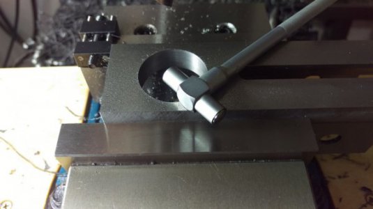
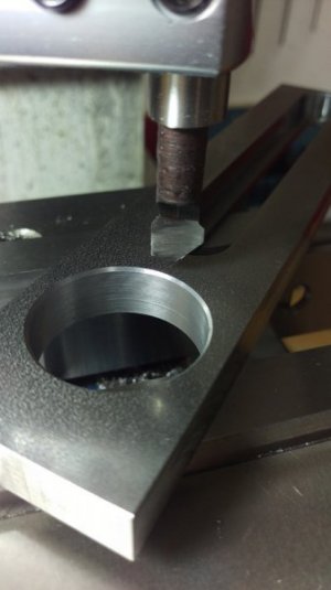
I made some more progress on my banjo project this evening. It was lightly finicky, as I was right at a crossover point in my telescoping gauge set. Other than that it was just drilling and bringing the holes to size with the boring head. The part I enjoyed most tonight, was making a chamfering tool for the boring head.


- Joined
- Feb 7, 2013
- Messages
- 2,486
According to the blogs (because you can always trust the internet . . .) there really isn't a good long term repellent for mice and rats. Depending on the ones you read, messing with their sense of smell doesn't work long term. They can live in sewers around sewer gas and smells that gag us, so dryer sheets, peppermint oil, etc. might work in the short term, but not for the long term. They are looking for a place of shelter and food. Remove those two and they go away. The farmers in our neighborhood use 5 gallon pails with antifreeze about halfway up. Float bird seed on the top and give them a nice ramp up to the pail. I've also seen a soda bottle with a stick through the middle (the long way) as an axle; axle holes drilled on either side of the pail. Coat the bottle with peanut butter and you've got a log roller for mice. By the way, the anti-freeze keeps the water from freezing in the winter.
Bruce
Mice don't have bladders so they leave a urine scent trail as they run along. If you are able to set a mouse trap
on the trail, it is very effective in catching them. I use peanut butter for baiting them in a wooden Victor trap
set with a hare fine release. If you have mice and are not catching them, you need to move the trap to along
the scent trail.
T
TOOLMASTER
Forum Guest
Register Today
they are strong little buggers...
F
Firestopper
Forum Guest
Register Today
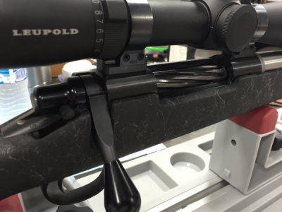
I had two weapons to work on yesterday. The first one, a .26 Nosler rifle that required a compensator to be "clocked" and a not so smooth bolt action that required a little lapping.
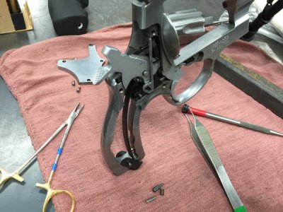
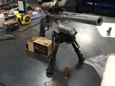
The second was a S&W .460 (hand cannon) that had a stuck firing pin.
On the Nosler, the owner refused to consider any type of peel washer of shim as he wanted to have the option of removing the break and not worry about loosing the said washer/shim. The 1/2"-28 threads provide about .036" of travel per revolution so the comp was torqued to 25 ft/lb and ended up at roughly 1' o'clock position prior to facing.
A 1-1/8" collet was a perfect choice as the collet had a small shoulder inside for the break to register allowing me to remove and test fit onto the barrel then back on the lathe without loosing my registration. I also set the compound perpendicular to the headstock and locked the carriage during set-up. A total of .0305" was faced off between two test fits and the muzzle break indexed TDC at 25 ft/lb. (even a blind squirrel find an acorn heheh). The second issue was a excessively tight bolt. The customer stated this rifle was "blueprinted" but having built a blueprinted bolt action myself, I was surprised at how tight this bolt fit and the lack of even contact the lugs provided. I mixed a slurry of fine pumice powder and gun oil and lightly coated the lugs contact points and parts of the bolt that showed contact. Cycled the hell out of the bolt up and down only while my son provided pressure with a long teflon dowel down the bore. This made sure the back of the lugs had pressure for even lapping. Once satisfied with even contact, the bolt was cycled back and forth polishing the black sharpie marks that where the tight areas. The slurry is very gentle and can take some time but its better than taking too much resulting in a sloppy bolt.
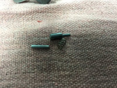
The S&W was torn down and I was able to free up the firing pin. The pin and return spring showed no ware but the entire area was fouled. I suspect the owner has been firing light bullets resulting in excessive flaming as too much gas is released as the bullet leaves the cartridge. I believe he needs to stick with 300+ grain bullets to prevent any damage flame cutting that could result in damage. I also honed the firing pin hole on the frame as it appeared to have a slight burr around the circumference.
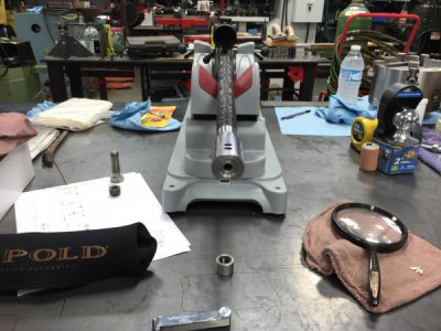
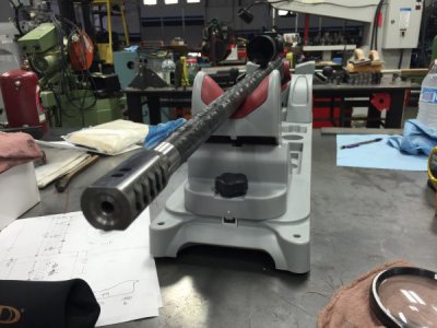
I always take extra time when it come to firearms as I don't work on them often, but its always the same group of guys that keep coming back for gun service or builds.
Thanks for looking.
Paco
The second was a S&W .460 (hand cannon) that had a stuck firing pin.
On the Nosler, the owner refused to consider any type of peel washer of shim as he wanted to have the option of removing the break and not worry about loosing the said washer/shim. The 1/2"-28 threads provide about .036" of travel per revolution so the comp was torqued to 25 ft/lb and ended up at roughly 1' o'clock position prior to facing.
A 1-1/8" collet was a perfect choice as the collet had a small shoulder inside for the break to register allowing me to remove and test fit onto the barrel then back on the lathe without loosing my registration. I also set the compound perpendicular to the headstock and locked the carriage during set-up. A total of .0305" was faced off between two test fits and the muzzle break indexed TDC at 25 ft/lb. (even a blind squirrel find an acorn heheh). The second issue was a excessively tight bolt. The customer stated this rifle was "blueprinted" but having built a blueprinted bolt action myself, I was surprised at how tight this bolt fit and the lack of even contact the lugs provided. I mixed a slurry of fine pumice powder and gun oil and lightly coated the lugs contact points and parts of the bolt that showed contact. Cycled the hell out of the bolt up and down only while my son provided pressure with a long teflon dowel down the bore. This made sure the back of the lugs had pressure for even lapping. Once satisfied with even contact, the bolt was cycled back and forth polishing the black sharpie marks that where the tight areas. The slurry is very gentle and can take some time but its better than taking too much resulting in a sloppy bolt.
The S&W was torn down and I was able to free up the firing pin. The pin and return spring showed no ware but the entire area was fouled. I suspect the owner has been firing light bullets resulting in excessive flaming as too much gas is released as the bullet leaves the cartridge. I believe he needs to stick with 300+ grain bullets to prevent any damage flame cutting that could result in damage. I also honed the firing pin hole on the frame as it appeared to have a slight burr around the circumference.


I always take extra time when it come to firearms as I don't work on them often, but its always the same group of guys that keep coming back for gun service or builds.
Thanks for looking.
Paco
- Joined
- Aug 26, 2013
- Messages
- 1,061
Dan,
I have a slightly different setup for the banjo on my PM lathe. Instead of using a dual lock nut set up like yours, the shafts themselves have a large square head on the end and do not have the integral washer like yours. You screw them in and use different thickness of washers to provide spacing away from the banjo itself, and then it is all secured with a slip-on washer that has a groove machined in it to slip over the square head to keep from rotating. The other difference is that my nuts that go on from the back of the banjo are elliptical style, flat on the sides with rounded ends. This allows them to slide up and down the groove of the banjo much easier. I will get some pictures posted for you to take a look.
Yea, I don't know why they designed it this way, for like an extra $2 worth of work the stock banjo could have been 10 times better.
- Joined
- Feb 17, 2013
- Messages
- 4,406
Way back in history I used to get my TV "fix" from a big-dish satellite system. The ~10' diameter dish had to be pointed toward various satellites in the Clark (geosynchronous) orbit to get different channels. A ball screw actuator was used for this purpose. When I changed to a little (digital) dish, I kept all the now nearly valueless hardware, hoping it would be useful someday.
Someday came a couple days ago when I decided to try adding a powered head lift to my round column mill. The ball screw actuator motor was to be the star of the show. It was originally powered by 36 VDC, but I decided to use the 24VDC accessory power supply I already have on the mill. 24V produced about 60 RPM, which I thought would be a decent speed. One turn of the crank moves the head about ¼", so 60 RPM would give me about ¼ inch per second.
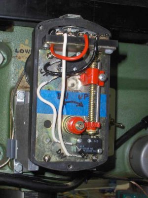
An added bonus to using this actuator motor is that the gear box includes a set of limit switches! They can be seen in the first photo. The red worm gear near the bottom is on the output shaft. It drives the gold-colored worm on the right. A tab on the nut activates the upper limit switch. An adjustable rod activates the lower one. Sweet! No limit switches to add externally, and no danger of jamming the head against a hard stop and frying the motor or stripping the gears!
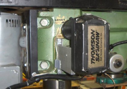
Mechanically the installation was pretty easy. I first milled some flats onto the cast iron mounting plate that holds the head elevating mechanism. The surface of the mounting plate, being a non-critical feature of the mill, was predictably out of true. Then I milled a couple of flats onto the front surface of the actuator and narrrowed the ring surrounding the output shaft. Next came a couple of side plates of ~½" aluminum to connect the actuator and the plate. This photo shows the completed mounting.
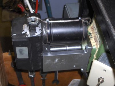
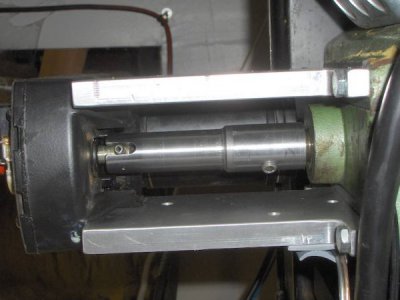
The last item was a shaft to connect the ⅜" cross-pinned shaft of the actuator and the 17mm (0.690") shaft of the elevating mechanism. Being lazy, I made this out of ½" threaded pipe (~0.624" ID) and a pipe coupling. The coupling was there to provide added thickness for the setscrew threads. I screwed the pipe sections (including a stub at the far end of the coupling) together tightly, using JB weld as a "permanent" pipe dope. Cut the end of the stub off even with the end of the coupling, then bored that end of the assembly to 17mm. I made a plug of paper towels and placed it about 1" from the other end of the pipe, then filled this in with more JB weld. When it was set, I driled it out ⅜", then milled a cross slot to accept the pin in the actuator shaft. I'm not sure I really needed the fill and the ⅜" hole, but this did help align things when I was match drilling between the actuator and the side plates. The two photos here show the finished assembly from top and bottom.
I placed the switch (DPDT momentary on/off/momentary on) in a Bud box near the head locking bolts. If nothing else, this relieved me of the inconvenience of having to go from one side of the mill to the other when changing height (the crank being on the side opposite the locking bolts!)
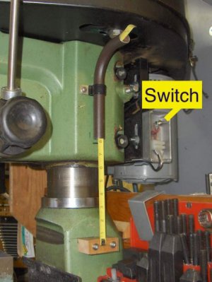
For a finishing touch, I added a rough-and-ready scale to indicate the approximate distance between the bottom of the quill and the surface of the table. The scale itself is just a section of tape measure I had floating around. The brown object attached to the mill head is part of an old lawn chair. The bottom end gives the reading. The curved top end guides the end of the tape measure away from the pulley box. The scale is mounted to a piece of oak screwed to the column base. A piece of acrylic holds it in place. Admittedly, this kludge will not work too well if I need to rotate the head. But it's a simple matter to unscrew the scale mount.
My one concern is how long the nylon gears in the actuator will stand up to the load involved in raising the head. Things seem to be doing well so far. If the actuator fails, I can always go back to the crank. Nothing I've done to the mill is irreversible.
In any case, I plan to phone the guy who originally installed my dish. I want to find out if he has any scrapped actuators floating around. If I can pick up a couple for cheap, I expect they'll be useful for other projects.
Someday came a couple days ago when I decided to try adding a powered head lift to my round column mill. The ball screw actuator motor was to be the star of the show. It was originally powered by 36 VDC, but I decided to use the 24VDC accessory power supply I already have on the mill. 24V produced about 60 RPM, which I thought would be a decent speed. One turn of the crank moves the head about ¼", so 60 RPM would give me about ¼ inch per second.
An added bonus to using this actuator motor is that the gear box includes a set of limit switches! They can be seen in the first photo. The red worm gear near the bottom is on the output shaft. It drives the gold-colored worm on the right. A tab on the nut activates the upper limit switch. An adjustable rod activates the lower one. Sweet! No limit switches to add externally, and no danger of jamming the head against a hard stop and frying the motor or stripping the gears!

Mechanically the installation was pretty easy. I first milled some flats onto the cast iron mounting plate that holds the head elevating mechanism. The surface of the mounting plate, being a non-critical feature of the mill, was predictably out of true. Then I milled a couple of flats onto the front surface of the actuator and narrrowed the ring surrounding the output shaft. Next came a couple of side plates of ~½" aluminum to connect the actuator and the plate. This photo shows the completed mounting.

The last item was a shaft to connect the ⅜" cross-pinned shaft of the actuator and the 17mm (0.690") shaft of the elevating mechanism. Being lazy, I made this out of ½" threaded pipe (~0.624" ID) and a pipe coupling. The coupling was there to provide added thickness for the setscrew threads. I screwed the pipe sections (including a stub at the far end of the coupling) together tightly, using JB weld as a "permanent" pipe dope. Cut the end of the stub off even with the end of the coupling, then bored that end of the assembly to 17mm. I made a plug of paper towels and placed it about 1" from the other end of the pipe, then filled this in with more JB weld. When it was set, I driled it out ⅜", then milled a cross slot to accept the pin in the actuator shaft. I'm not sure I really needed the fill and the ⅜" hole, but this did help align things when I was match drilling between the actuator and the side plates. The two photos here show the finished assembly from top and bottom.


I placed the switch (DPDT momentary on/off/momentary on) in a Bud box near the head locking bolts. If nothing else, this relieved me of the inconvenience of having to go from one side of the mill to the other when changing height (the crank being on the side opposite the locking bolts!)

For a finishing touch, I added a rough-and-ready scale to indicate the approximate distance between the bottom of the quill and the surface of the table. The scale itself is just a section of tape measure I had floating around. The brown object attached to the mill head is part of an old lawn chair. The bottom end gives the reading. The curved top end guides the end of the tape measure away from the pulley box. The scale is mounted to a piece of oak screwed to the column base. A piece of acrylic holds it in place. Admittedly, this kludge will not work too well if I need to rotate the head. But it's a simple matter to unscrew the scale mount.
My one concern is how long the nylon gears in the actuator will stand up to the load involved in raising the head. Things seem to be doing well so far. If the actuator fails, I can always go back to the crank. Nothing I've done to the mill is irreversible.
In any case, I plan to phone the guy who originally installed my dish. I want to find out if he has any scrapped actuators floating around. If I can pick up a couple for cheap, I expect they'll be useful for other projects.
- Joined
- Nov 23, 2014
- Messages
- 2,606
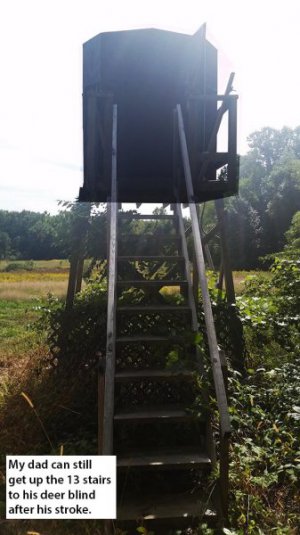
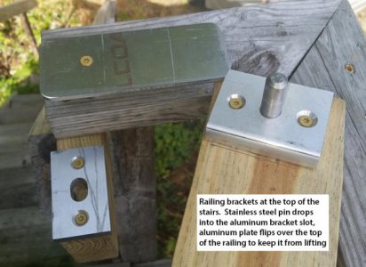
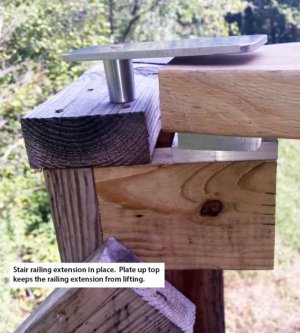
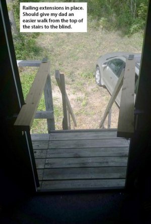
POTD was helping my 80-year old dad and stroke victim make the awkward transition from the top of his deer/turkey blind's stairs to the blind itself. Longest 4-foot journey of his life; he works his way around the blind railing to the door, then hangs on the window sills to get to his seat. Time to help him out and work the problem.
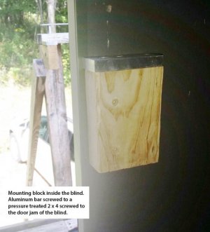
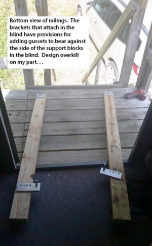
Made some easily removable railing extensions that bridge the gap between the top of the stairs and into the blind. Brackets are machined 1/2" thick aluminum, pins are stainless steel. Should help a ton getting him into his seat. Deer season (bow) in Michigan starts 10/1, nothing like waiting until the last second to get a project done . . .
Bruce



- Joined
- Feb 8, 2014
- Messages
- 11,144
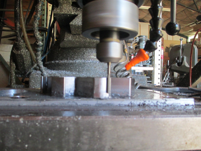
Here is my POTD. Finish pass on a part I'm building
This one is a nail biter... ...0.157, 4 flute, HSS end mill going 1.030 deep in steel, the shank of the end mill is reduced to just under the size, about 0.150. 0.030 DOC, 0.010 cut width, 5 IPM, 90 FPM, about 2100 RPM, 0.0005 chip load. About 425 minutes of run time, so pretty much an all day project.
I needed this size end mill to minimize the corner radii to fit another part. The smallest end mill I had with a 1 inch cut length. You can't see it in this picture (on purpose) but there is no way to get into the corners with anything else I have.
About 0.750 deep and about 280 minutes into the process in the picture. That's about 1.5 inches of stick out on a 0.157 end mill Thank God for CNC machines, I could never do this by hand.
I was going to work on software for Alloy's Shizuoka, but I let the computer connect to the network, and Windows 10 has been updating for the last 2 hours. I hate computers I'll get to that project in a bit, I hope.
This one is a nail biter...
 ...0.157, 4 flute, HSS end mill going 1.030 deep in steel, the shank of the end mill is reduced to just under the size, about 0.150. 0.030 DOC, 0.010 cut width, 5 IPM, 90 FPM, about 2100 RPM, 0.0005 chip load. About 425 minutes of run time, so pretty much an all day project.
I needed this size end mill to minimize the corner radii to fit another part. The smallest end mill I had with a 1 inch cut length. You can't see it in this picture (on purpose) but there is no way to get into the corners with anything else I have.
About 0.750 deep and about 280 minutes into the process in the picture. That's about 1.5 inches of stick out on a 0.157 end mill
 Thank God for CNC machines, I could never do this by hand.
I was going to work on software for Alloy's Shizuoka, but I let the computer connect to the network, and Windows 10 has been updating for the last 2 hours. I hate computers

