2016 POTD Thread Archive

I'm still working on my Yamaha XS650 project and fitting the Buell forks to it. One challenge in this is the front brake. I was planning to use the single Buell 340mm rotor because I have a caliper and it would be way lighter than a dual caliper set up with two 290mm rotors from a Yamaha XS1100 that I also considered.

I bought a used Buell brake rotor on eBay and was going to machine an adapter to make the 5 bolt hole Buell rotor fit the 6 bolt hole Yamaha wheel. Unfortunately the Buell rotor was bent. I shot a video and sent it to the vendor and he promptly refunded my money and told me to scrap the rotor.

I decided that the bent Buell rotor might be usable if only the aluminum carrier is bent and not the stainless steel braking surface. I removed the 9 buttons attaching the 2 parts together and checked the steel part on my surface plate and it appears to be dead flat. I decided to attempt to make a hybrid rotor using a Yamaha disc and the outer part of the Buell rotor.
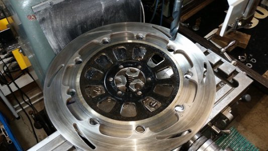
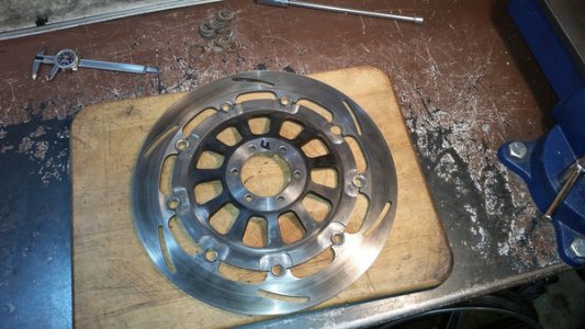
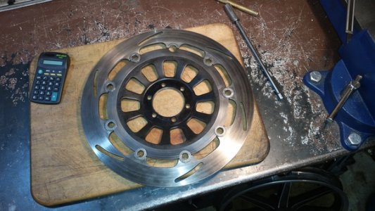
Here's the Buell rotor with the center removed laying over the Yamaha one. This might work!
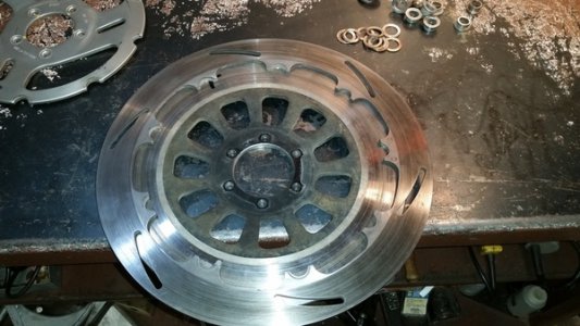
20161003_164431_zps2gjfyy7t.jpg

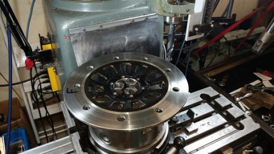
I measured the button hole radius on the mill and laid out and spot drilled the 9 holes in the Yamaha rotor.
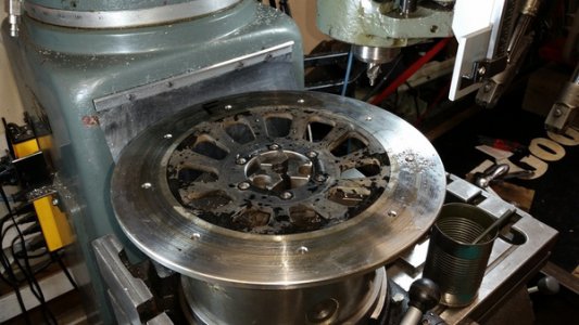
20161007_120747_zpsnkyvydaj.jpg

I then drilled them to 21/32" or .656" matching the size of the holes in the Buell rotor.
20161007_123902_zpsfvmxtoxx.jpg

When I checked the hole layout against the Buell rotor it matched perfectly, that was a relief.

20161007_123902_zpsfvmxtoxx.jpg

20161007_124146_zpspfpikuug.jpg


th_20161007_124415_zpszoqcubnq.mp4.jpg

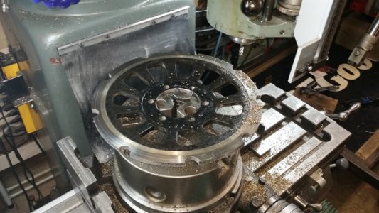
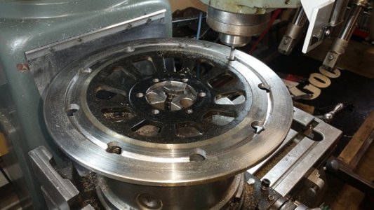
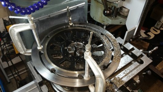
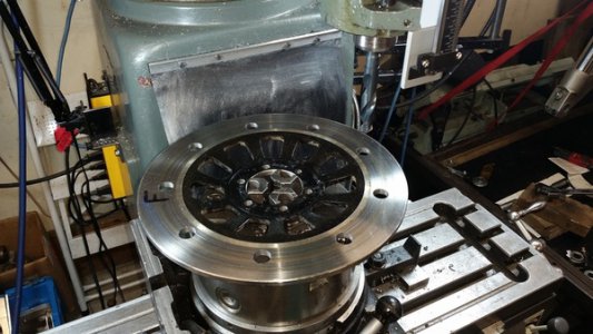
I measured the OD of the Buell rotor carrier and set up a 1/4" end mill to cut out that circle on the Yamaha rotor.
20161007_131720_zpszvtirgs3.jpg

20161007_133113_zpsky5zcq80.jpg

20161007_133241_zps4ay7n0uh.jpg

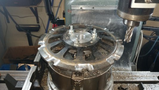
The Yamaha rotor is 2mm thicker than the Buell one so I milled a pocket at each button location so the thickness of both parts will be the same where the buttons mount.
20161007_161701_zpsoli063sh.jpg

I assembled the parts temporarily to check the fit with the old buttons and it looks good. Next I have to pick up some 303 stainless bar to make the new buttons with.
20161007_162453_zps4dqyme3r.jpg

20161007_163803_zpsobobpzzd.jpg

Time will tell if this is going to work out but all I have invested so far is the Yamaha rotor which I was not going to use anyway.
We always called these builds as Frankensteins. Using several brands to make a useable one. Looks good or even better, nice job so far.

20161007_123902_zpsfvmxtoxx.jpg
 
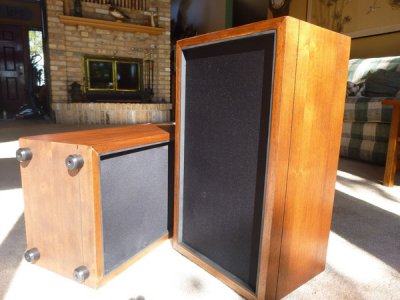
Not as exotic as custom bike parts but I spent the day in my shop refurbishing my old stereo speakers. I purchased these things in '69 and they still sound great but they were starting to look like crap. They were sun faded and had been used as plant stands so they had some major water stains. I was just going to paint them black but at the last minute I decided to see if I could just refinish them. A little sanding and some oil finish and the wood turned out great. Of course the new speaker grill cloth really helps too. I then went to my lathe and turned down some Delrin to make feet for them as they will be going on a wood floor now. They will probably outlast me now.
speakers.jpg
 
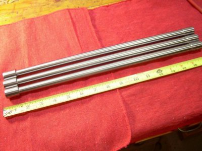
Any particular advantage to that one over making one from ground drill rod? That has been my plan. I even picked up several pieces of drill rod for 50¢ per pound from a surplus shop the other day (though I haven't tested them for straightness yet).

I do it the other way Mr Pete showed.

 
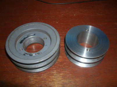
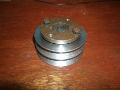
This past week with the hurricane coming I decided to get my generator out and get it running just in case. I built this about 15 years back and never used in an emergency. I must have done a good job of putting it away last time as it took very little work to get it running again.

After running it for awhile I remembered that the voltage was a little low (103/208) at full throttle and that I was going to fix that way back when. I could have adjusted the governor for a higher RPM but I decided to change the driven pulley instead.
The pulley has a taper lock bushing and the smaller size pulley is available for around $25 but where is the fun in that.

GEDC2744s.jpg

GEDC2738s.jpg

I am pleased with the result.

Thanks for looking

Ray
 
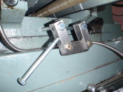
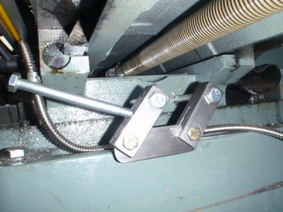
Like pretty much everyone who's ever had a round-column mill/drill, I got tired of getting my hand dirty on the leadscrew while locking or unlocking the Y-axis. When i started to plan it out, I realized it was a pretty quick project. I won't bore you with a step-by-step description.

Here's the finished product. I do have some 1" screw-on balls that I was planning to use on the end of the handle, but there isn't enough clearance against the base casting. I may put a slight bend in the handle to allow it, but it seems to work well as is.

Unlocked.
PA090099a.jpg

Locked.
PA090100a.jpg

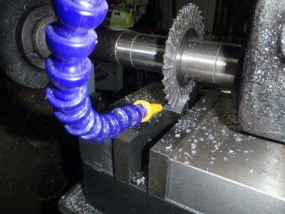
Okay. I'll give you one little detail. I cut the slots on the arms at 30 degrees to clear the link bar at both ends of travel. I clamped the bars at that angle and used one of my smallest slitting saws to make the cut.
PA090097a.jpg

I really like the way it works. Quick, clean and it really holds.
 
Johnnyc14,
Nice job on the brake rotor. I'm really enjoying following along with your SX650 project.
 
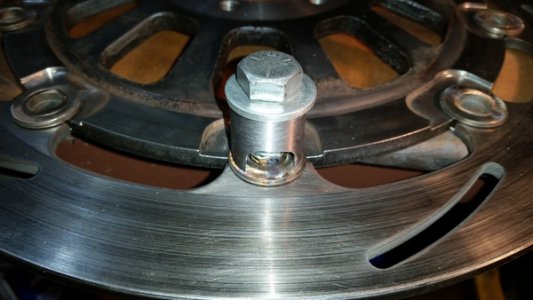
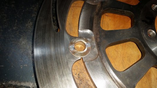
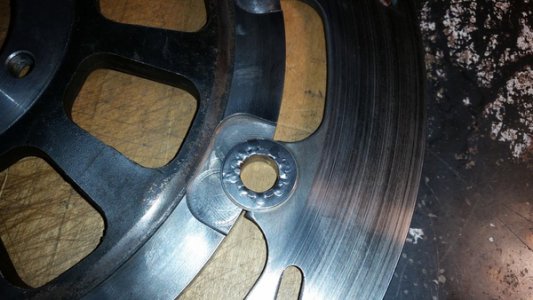
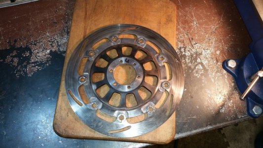
To finish the front brake set up on the XS650 my plan for rotor buttons was to make a 2 part system where the 2 parts would thread together instead of the press fit of the originals. I decided instead to use the old rotor buttons rather than make new ones. The originals are in the shape of a tube with a raised lip on the outer edge and a conical spring washer on the back side, then another thicker washer was installed over the tube and the tube was peened over to retain the washer. Not very strong but there should be no lateral forces so strong enough. When I removed them I used a disc sander and removed just enough of the tube to be flush with the outer edge of the washer then used a brass drift to punch the tubular buttons out. I thought that I should be able to just put the old buttons, conical springs and washers back on and make a tool to push the washers over the buttons until flush with the edge and then fusion weld them in place with the TIG welder. If it didn't work out I could still make new buttons. I made up a very simple tool to hold the assembled buttons together with 2 openings to allow 2 spot welds on each. I ground the TIG tungsten to a very sharp point and it turned out well.

20161010_124916_zps9en3p3oe.jpg

20161010_124924_zpsedonstoe.jpg

After I got each one spot welded in 2 places I continued without the holding tool and add 1 spot weld at a time, with plenty of cooling time between welds, until a total of 10 welds were applied to each button washer. I'm confident this will be at least as strong as the originals.

20161010_132020_zpss4pr3kbs.jpg

20161010_132009_zpszermmcso.jpg

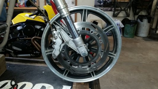
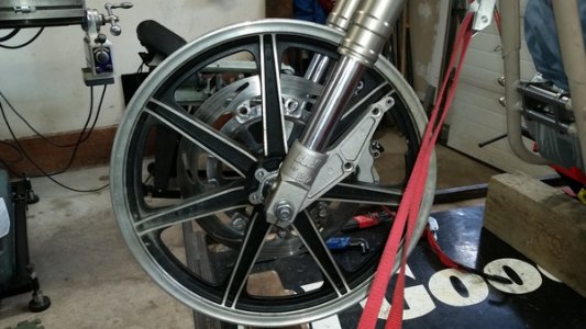
Then I installed the rotor to the wheel and the wheel to the forks and checked the rotor for run out with dial indicator. Less than .001", good enough for me. I had to use a .075" thick spacer between the fork leg and the caliper to center the caliper on the rotor.

20161010_133146_zpsaoycm4ph.jpg

20161010_133203_zpsx7pdmsjc.jpg

20161010_133749_zpszmmijt9q.jpg

20161010_133959_zpshhdazzsy.jpg

20161010_134009_zpsuiqjtya0.jpg

I'm really happy with how it turned out, the front brake on this project was one of the things I did not have a plan for.
 
Back
Top