-
Welcome back Guest! Did you know you can mentor other members here at H-M? If not, please check out our Relaunch of Hobby Machinist Mentoring Program!
- Forums
- THE PROJECTS AREA
- PROJECT OF THE DAY --- WHAT DID YOU DO IN YOUR SHOP TODAY?
- Project of the Day Mega-Thread Archives
You are using an out of date browser. It may not display this or other websites correctly.
You should upgrade or use an alternative browser.
You should upgrade or use an alternative browser.
2016 POTD Thread Archive
- Thread starter sanddan
- Start date
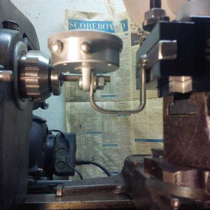
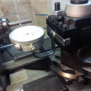
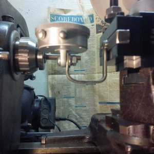
Mostly finished up my lathe height gage. Botched the first base, so started again from scratch:
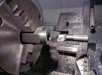
Got some small boring bars from Maritool that were a huge improvement over the cheap import brazed carbide boring bars I used on the first attempt. This bar, which I could use after I opened the hole up to about 3/4", is from latheinserts.com.
On the second threading attempt I used a dead center instead of the spring-loaded one and didn't do any tapping under power. The botched base had a slightly canted bore and I think it was from the tap.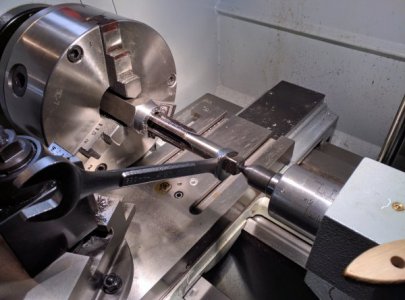
Finished up with some knurling and then split the gage surface off the top and faced/chamfered both sides. Mostly finished product:
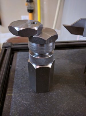
Knurling on the base didn't come out as good as on the top; one of the knurls quad-tracked. I need to add a brass-tipped set screw to hold the adjustment, and might add some of that black crinkle paint that mark_f is so fond of.
I'm toying with the idea of a magnet in the base like the one oxtool did in his video, but I'm afraid it will collect swarf and keep the base from seating square to the cross-slide.
It would also be nice to case-harden the gaging surfaces, but I don't know how feasible that is with 12L14 and whther it will distort the parts and require some remedial work on a surface grinder.

Got some small boring bars from Maritool that were a huge improvement over the cheap import brazed carbide boring bars I used on the first attempt. This bar, which I could use after I opened the hole up to about 3/4", is from latheinserts.com.
On the second threading attempt I used a dead center instead of the spring-loaded one and didn't do any tapping under power. The botched base had a slightly canted bore and I think it was from the tap.

Finished up with some knurling and then split the gage surface off the top and faced/chamfered both sides. Mostly finished product:

Knurling on the base didn't come out as good as on the top; one of the knurls quad-tracked. I need to add a brass-tipped set screw to hold the adjustment, and might add some of that black crinkle paint that mark_f is so fond of.
I'm toying with the idea of a magnet in the base like the one oxtool did in his video, but I'm afraid it will collect swarf and keep the base from seating square to the cross-slide.
It would also be nice to case-harden the gaging surfaces, but I don't know how feasible that is with 12L14 and whther it will distort the parts and require some remedial work on a surface grinder.
- Joined
- Dec 22, 2015
- Messages
- 561
Decided I should clean the ways on the mill drill and in the process noted the lead screws were kind of sticky. Checked underneath and sure enough, I still haven't worked all of the shipping gunk out off of them. So I figured I would pull the leadscrews (if that is the right term) and clean them properly.
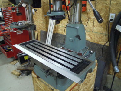
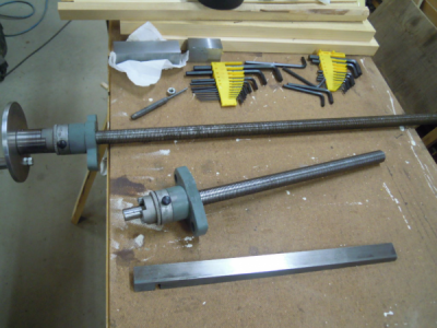
After pulling the short screw (can't remember if that is the x or the y) I noted there was a defect in the brass guide. Looked like a piece was missing.
Hard to see in the pic but it is on the right side about 4 threads back.
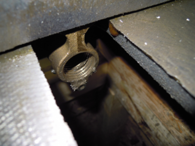
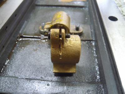
But after pulling the top table off I could see that there was a slot in the screw guide for its leadscrew. mmmmm I bet that is for backlash adjustments. Maybe it's ok after all.
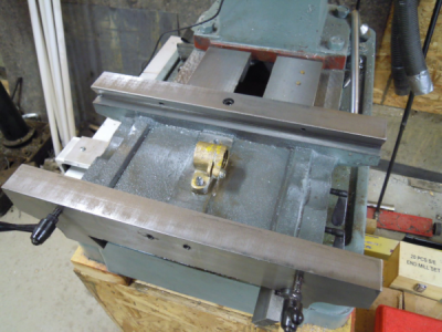
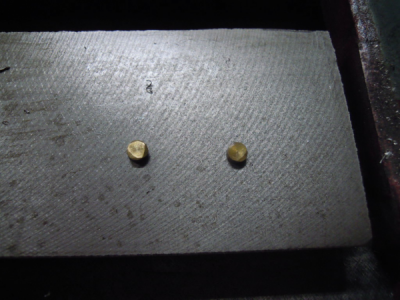
When I cleaned the top dovetails I heard a clicking sound as something hit the floor. I wasn't aware of these little plugs that were at the ends of the table locks.
They fell out. Try and find those in a mess of swarf that's laying on the floor all around the base of the mill.
So I pull the bottom table and it looks the same as the top. Obviously it's for backlash adjustments ........ duh .
.
Life is good again and now I can finish cleaning it all up, lubing it and putting it back together so I can play, I mean work on some essential stuff.
Sure looks strange without the tables.
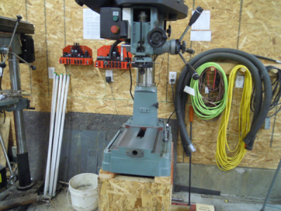
Well I finished lunch and a coffee so it's back to the shop for some cleaning and reassembly.


After pulling the short screw (can't remember if that is the x or the y) I noted there was a defect in the brass guide. Looked like a piece was missing.

Hard to see in the pic but it is on the right side about 4 threads back.

But after pulling the top table off I could see that there was a slot in the screw guide for its leadscrew. mmmmm I bet that is for backlash adjustments. Maybe it's ok after all.

When I cleaned the top dovetails I heard a clicking sound as something hit the floor. I wasn't aware of these little plugs that were at the ends of the table locks.
They fell out. Try and find those in a mess of swarf that's laying on the floor all around the base of the mill.

So I pull the bottom table and it looks the same as the top. Obviously it's for backlash adjustments ........ duh
Life is good again and now I can finish cleaning it all up, lubing it and putting it back together so I can play, I mean work on some essential stuff.

Sure looks strange without the tables.

Well I finished lunch and a coffee so it's back to the shop for some cleaning and reassembly.
- Joined
- Jul 11, 2014
- Messages
- 496
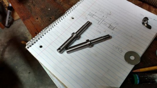
Decided to do something (finally) with a box of number 10 Hardinge collets I got for $1.27 plus shipping off E-bay more than a year ago. So I started on the draw-bar to make them useful for my grizzly G9972 lathe.
View media item 95561
I use a length of 1/2" pipe I had laying around. Threaded one end 32 TPI. Cut to length then turned a handle from a failed project of a couple of years ago, never toss those things out doncha know. Made a 'spacer' for adjustment from some brass in the bin. Still need to turn the tapered sleeve for closing the collet and fit it to the spindle. Won't know the actual final length until I turn that sleeve.
A productive five hours spent in the shop.
- Joined
- May 16, 2016
- Messages
- 1,698
Jon, I can't see your images lately.
Is anyone else having that problem?
Yes I'm also unable to see the pictures posted on about 20-30 % of posts. They just show up as a thumbnail with a red X over it. I believe that is a failure to load correctly. At first I thought it was my computer, but now I think its the device or method these people are using, because a number of other members are having the same problem.
- Joined
- Aug 22, 2012
- Messages
- 4,121
Yes I'm also unable to see the pictures posted on about 20-30 % of posts. They just show up as a thumbnail with a red X over it. I believe that is a failure to load correctly. At first I thought it was my computer, but now I think its the device or method these people are using, because a number of other members are having the same problem.
Just click reply for for messages with the red crossed images and read it in the box at the bottom of the page. Annoying but works. Delete the reply when finished.
- Joined
- Oct 4, 2014
- Messages
- 172
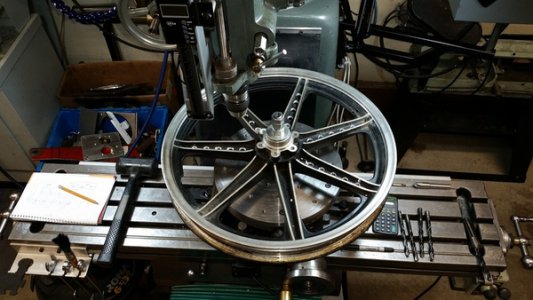
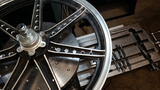
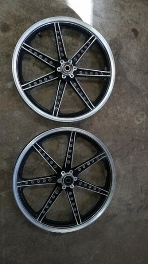
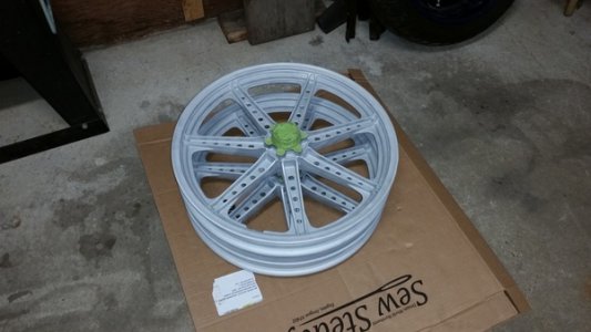
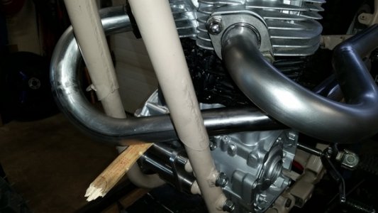
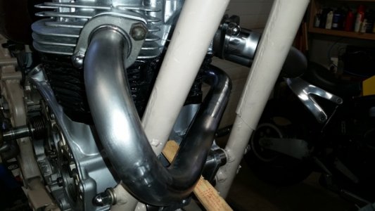
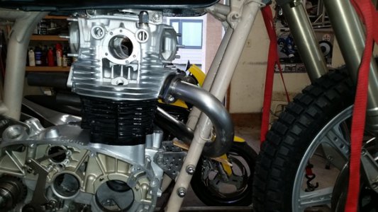
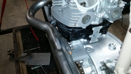
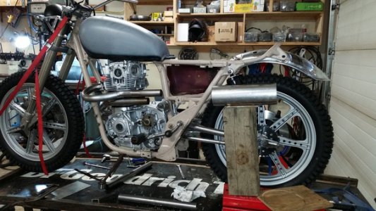
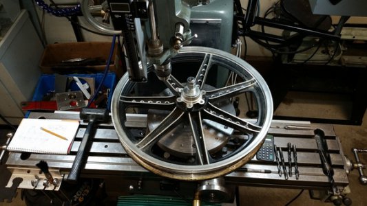
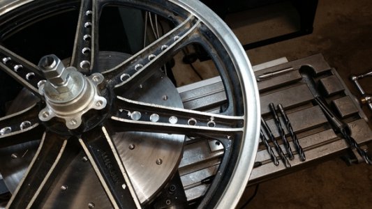
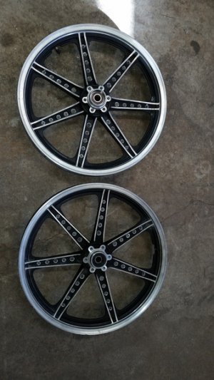
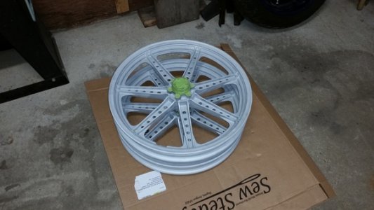
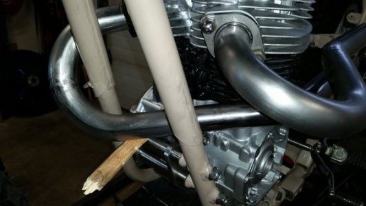
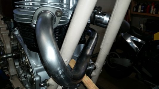
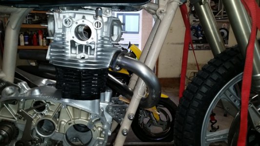
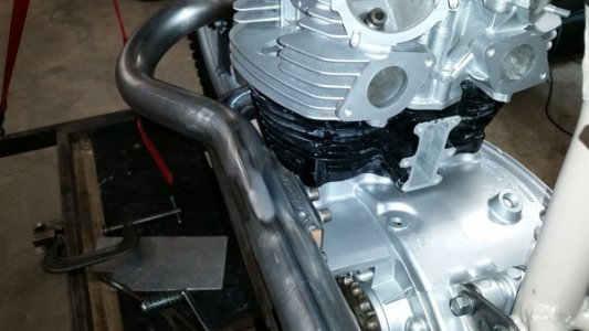
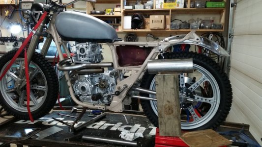
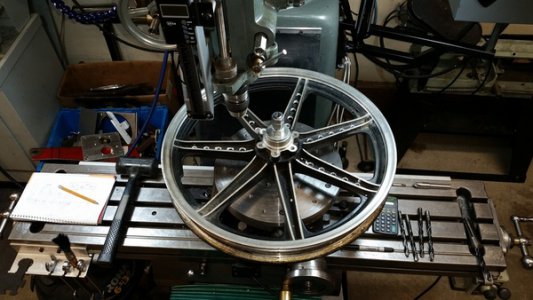
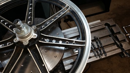
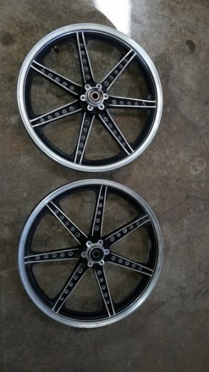
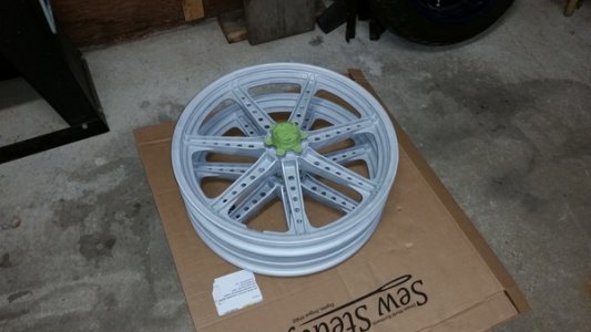
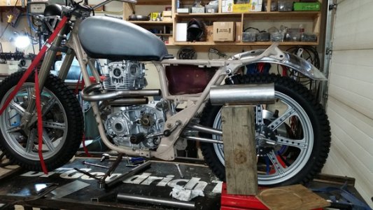
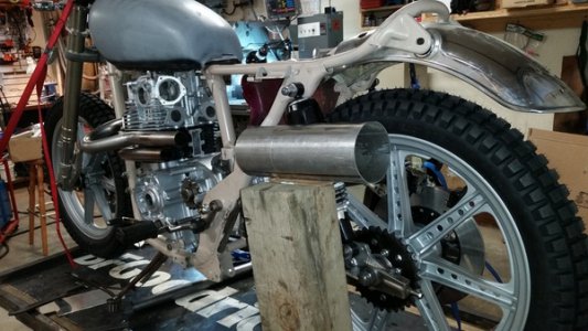
That's some quality pipe work, nice job.A little more progress on my XS650 project. I glass bead blasted the 19" wheels and drilled each spoke with 5 evenly spaced holes and powder coated them in a cast aluminum color finish. I mounted a couple of Shinko 241 tires that resemble the old Dunlop Trials Universal tires that came on Yamaha Enduros in the 70's, both in 3.50" X 19" size. I'm thinking about front fender options now and leaning toward a plastic dual sport fender. I took the one off my DRZ400 (21" front wheel) and temporarily attached it with zip ties. It looks pretty good so I ordered a black UFO fender for a Honda CR85 that will fit better with the 19" wheel. This weekend I'm going to work on an exhaust system and test my TIG welding skills.
Last time Dime City had a free shipping deal I ordered a TC Bros exhaust kit from them. Nice quality mandrel bends and header flanges for the money.
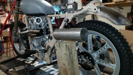
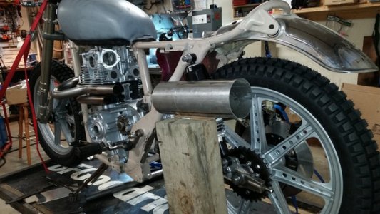
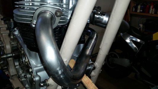
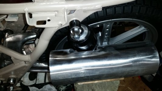
I've decided to go with a left side high pipe system something like my Honda CL450 has, I'm a sucker for high pipes!
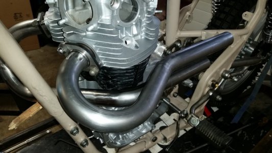
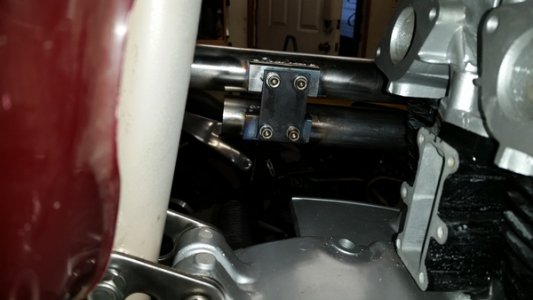
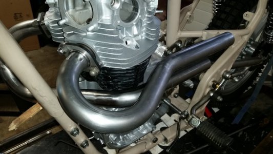
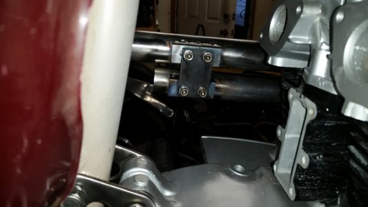
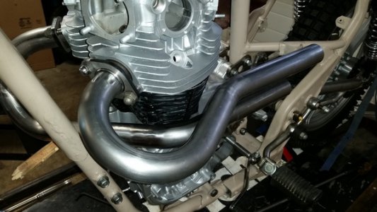
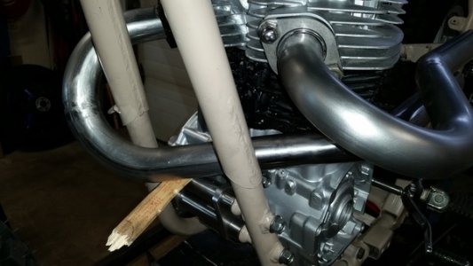
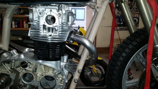
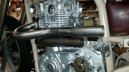
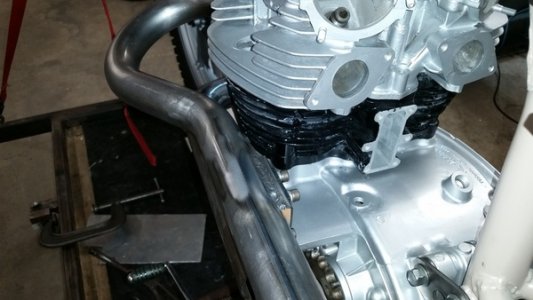
My TIG welding skills are pretty weak so I decided to MIG weld all the pipe joints and then dress the welds down with a flap wheel and polish them with a Roloc disc. I spent a few hours in the garage today and came up with this for head pipes. The mild steel is easy to work with and if it turns out OK I will probably get it ceramic coated.
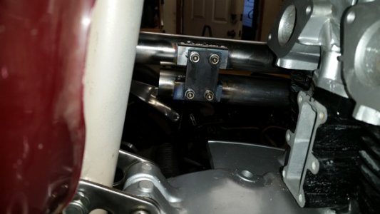
I cut some 1" square tubing into a couple of C shaped bracket and TIG welded some 1/4" nuts to the inside, then TIG welded these bracket to the inside of the head pipes for support and also to serve as a front mount for a heat shield I will build later.
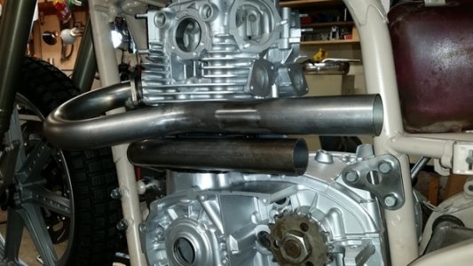
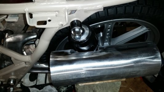
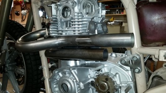
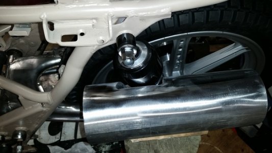
I'm working on an idea for a single muffler that will involve a 1' section of 4" exhaust pipe with machined aluminum end caps. I roughed out the idea like this.
To be continued.


- Joined
- May 16, 2016
- Messages
- 1,698
Wife gest upset with me at times for saving all that stuff, That is until she needs something fixed and I just happen to have the stuff that will work saved out in the shop somewhere. But by the next day it is back to the complaining.
That's what they do best when confronted with something that they don't understand, like a man who can actually do stuff.
Last edited:
- Joined
- Nov 23, 2014
- Messages
- 2,607
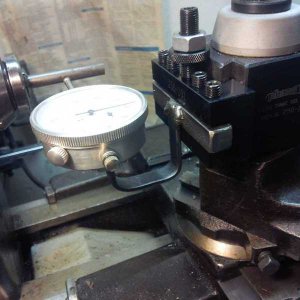
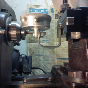
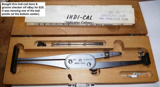
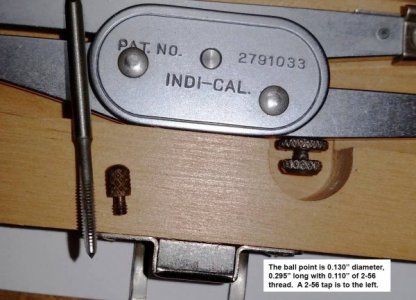
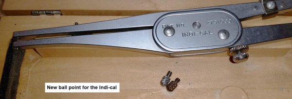
One operation I struggle with is measuring the depth of an internal groove or relief. I have a set of 0.375” – 1.375” inside dial calipers (run around $55 on eBay) which work pretty well. I’d been eyeing a product called “Indi-cal” for some time, picked one up off eBay for around $25. It’s advertised to be able to check internal bores and grooves from 0.200” to 6.000”. Only problem with the unit was one of what the instructions call a ball point was missing.
The ball point is about 0.130” in diameter, 0.295” long with a 2-56 thread 0.110” long on one end. Looked up a 2-56 thread in Machinery’s Handbook; 0.086” OD and a #50 tap drill.
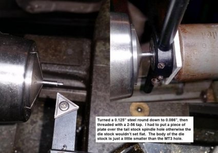
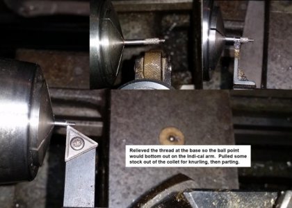
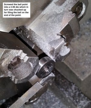
I leave a 5-C collet chuck on my Clausing lathe for just these occasions. Chucked up a piece of 0.125” CRS and turned down a shoulder to 0.085”. Very carefully threaded with a 2-56 die, knurled the OD and parted off the point. Screwed the point back into the die which was chucked up on my Grizzly G0709 for filing the ball on the point. Fits perfectly.
I'll post a thread in the Metrology section in a day or two on how the Indi-cal works.
Bruce


