2017 POTD Thread Archive

I am finally able to finish up some projects that have been put on hold until I got my mill.

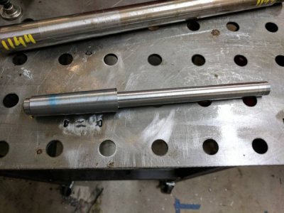
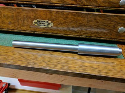
This is my action truing jig. Just need to buy some 1/2"-20 set screws and brass tip them. There are a lot of plans to build these to be inserted into a 4 jaw chuck but I liked the idea of just being able to put it on the lathe.

IMG_1809_zpsljh0fuso.jpg


IMG_1808_zpsjrfogl2w.jpg


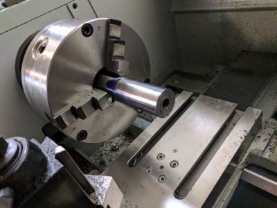
I needed a jack to stabilize the jig when I was drilling but I don't have any. I got a nut from my clamping kit, cut a stud from some ready rod (studs in kit were too long) and used a hex spacer nut.

d143b427-d2a4-449b-98a8-656d1dfbacf6_zpspafyvd45.jpg
 
Looks good, That looks kinda like the one I started for BamBam, He had to drill the holes etc, as I do not have a mill. They work great, but you need a bit of a way to use a handle to help turn it when truing it up. as just grabbing it if you have small hands is a pain.
 
I went and tried to turn it and I can spin it rather easily with lathe in neutral.
If I want to leave lathe in gear, I can also turn the spindle at a snails pace and stop it on a dime with the VFD that Mark (mksj) built for me.
 
  • Like
Reactions: Guv
I’ve got a project requiring TIG welding 0.036” thick sheet steel. I figured a roll of 0.023” MIG wire would work for the filler rod. Now just need a delivery system . . .

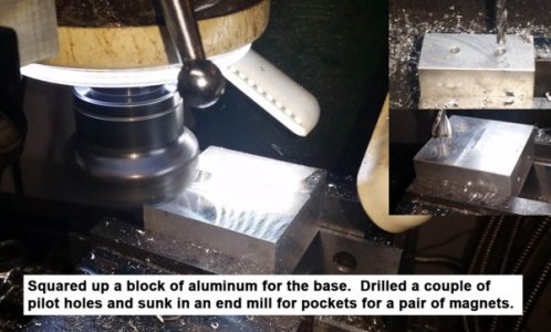
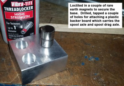
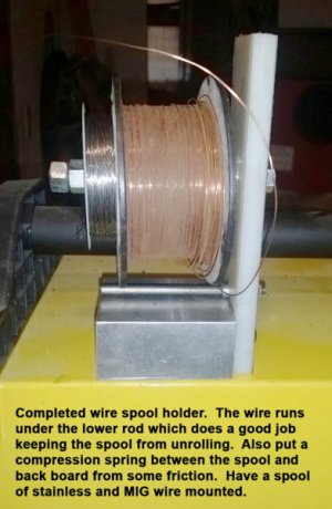
Made a spool holder with an aluminum base and an insulated plastic backboard to hold the wire. There are a couple of rare-earth magnets in the base to keep it in place. There’s a compression spring on the axle post to add some friction. The axle (bolt) is long enough to mount a small spool of stainless wire and the MIG wire. There’s also a small horizontal post near the bottom that keeps the spool from uncoiling when the wire is released.

It works pretty well. My TIG welding still needs some practice, but at least I can’t blame having filler wire available to follow the puddle. Oh, also discovered it’s kind of important to have an insulating pad on the welding table. I ground the table instead of the work. Naturally, if the wire touches the table it’s grounded and the arc from the tungsten jumps from the work to the wire.

Bruce

20170506_152242.jpg 20170507_120414.jpg 20170509_190347.jpg
 
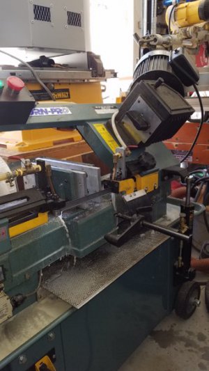
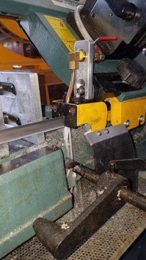
Well go caught up on a few to do things on my procrastination list. First off was adding a second coolant line to the horizontal band saw to clear the chips so they do not get ground into the drive wheels. Problem is that these machines are an amalgamation of metric and American sized parts/threads so it is always a guessing game to name that thread. Also the stock coolant valve was a brass body with a steel ball and shaft, the thing froze up, so everything got replaced. Milled a second support for another valve out of aluminum with SS hardware, had to use 5/16" tubing and scrounge a coolant branch T that would fit and tucked the second hose around to the back. Also added a splash flap to keep the coolant in the machine and not on my leg. Bad dog, you can see the pee spots on the floor from before the flap. The second coolant stream now does a very nice job of flushing the chips off the blade.
20170510_125849.jpg 20170510_125924.jpg

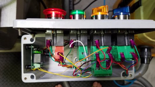
Next project, that had me puzzled for days was my mill has an additional control systems for an auto start and auto reverse triggered by proximity sensors and the reverse point is set by the spindle lock. Problem was that there is a latching circuit that didn't unlatch when the machine was set back to manual. If one forgot to hit the stop button after engaging the auto start the mill could restart when set to manual mode, not happy with that. The wiring was such that you needed a delay timer that would open the power circuit for 2-3 seconds and then reset the power after returning to manual. A simple relay timer didn't cut it, so I used a dual opto coupled relay board and added a timing element to one relay. So the system is only on when both relays are normally closed (manual) or both are on (auto on/reverse). Because of the stagger trigger circuit in the relay timing, there is a 2 second break between the first and second relay opening so that kills power to the control board latched relays, and resets the system. I know, Blah, Blah, Blah... but happy I found a simple solution at the end of the day and installed it this morning and it worked! The added dual relay timer is on the left in the switch control pod.
20170514_122636.jpg

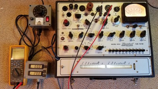
Did some work on one of my many tube testers... calibration time. Used the mill to make the external control box and set the voltage to align with my Fluke volt meter. My nerd hobby.
20170513_164650.jpg

Wife is traveling so time to get caught up. :chunky:
 
Last edited:
Very slick setup on the blade cleaner. Nicely done. Mike
 
Well, another project I started got put on hold because my internal groovers won't hold an insert for the size groove I want. Sooo, off came the chuck with piece intact, threw on a different chuck and started a different project. Here's a grinder hub for the B&S #2. It will have some special features that I'll show later. I decided to make it from two pieces of 1045. The collar and disk were deeply chamfered (almost 1/4") for solid TIG and weld-up. Oh man, I'm covered in 6's and blisters.

BTW: No, I didn't TIG weld it in the vise... It was 750 F when I was done welding it so, clamping in the vise makes it cool off faster. -And yes, I used ER80S because of the high carbon 1045.

Ray


View attachment 51065View attachment 51066View attachment 51067View attachment 51068View attachment 51069

View attachment 51065 View attachment 51066 View attachment 51067 View attachment 51068 View attachment 51069
Good looking weld
 
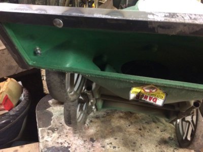
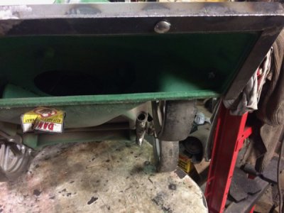
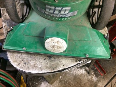
Made a wear strip for my Power Vacuum. The plastic housing wears, both on the sides and the bottom, so I made a wear strip out of 1/8" sheet metal.

IMG_0876.jpg
IMG_0878.jpg
IMG_0879.jpg

Now, it's off to be painted...

I'll see how this works, and if it works ok going over uneven ground or if it digs in very much (even the plastic will on more uneven ground). If it does, I might try running a thicker bead of weld on the inside of the leading edge, then grind the outside to be more round. And then, if that still digs in, I might try to use thinner sheet metal and use a metal brake to make another wear strip with an even more round leading edge.
 
Back
Top