Enterprise 1550 lathe restore

I got the gearbox cover off today and man it looks gorgeous inside. Shiny clean and oiled.
For the speed change lever, should it have a detent to snap into each gear? Right now it just smoothly rotates. Also what does the lever coming straight out of the speed dial? It won't go all the way to the right into the second position?
Also what is the S shaped tube for, the cover has a plastic cap on it to access that.
Looks great! Had a good top cover gasket and the vent hole must not be exposed, Lucky for you.
 
I'm certain there should be a detent for the lever-if the lever can freely move when running then a gear crash could occur.
As for the other lever you'll have to observe closely what happens in the gearbox to determine it's function. You need to memorize all the functions anyway so might as well start there.
S-tube is a vent like Harry said above
 
Last edited:
Thanks for all the help guys, Ill have to get the speed selector apart and see if the detent is stuck or broken spring or something. As for the other lever I can't see it doing anything in the gearbox so still not sure what it does.
 
Yes. The 4 position gear selector does have a dedent so you can feel it click into each position. There is a ball and spring system in behind the selector handle.

Yes. The two speed Hi/Lo selector should go up against the two respective gate positions. On my machine the gate cut outs, where the handle drops into the space for it (pushed by a small spring) were not really well positioned. It would occasionally pop out of Hi range. I took the cover off and worked out what handle position was needed to have full engagement of the Hi range gearing. Then I made a new little gate piece for the new position. I had lived with the problem for about 35 years, only just fixed it about 5 years ago - never had any more issues with it coming out of gear.

The goofy little U oil pipe? That is just a bit of Enterprise bling. The oil pump delivers oil to the top cavity along the top of the gear box, so that all the bearings receive oil (gravity feed from the top cavity down various passages). The U pipe shoots the oil up against the plastic sight glass on the lid so the operator can see the pump is delivering oil up to the top. I have never had a problem with the oil pump on mine, so I can always see it blasting away in the sight glass. When running in reverse, the oil is not pumping - but I believe there is a comment in the manual that reverse running is not a problem for headstock lubrication. Generally one does not run a lathe in reverse a whole lot anyway. I run in reverse occasionally, never had a problem. I believe the oil pump is on the chuck end of the input shaft (check it out in the manual).
Wow, thanks for all that info. So apparently my speed selector has some issues and the hi/low lever isn't working as it should
 
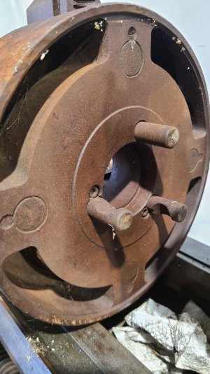
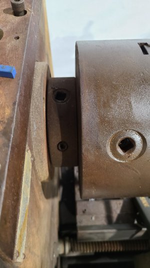
Hi everyone, had to take a break from the lathe for a while, but I'm getting back to it now. So I got the detent fixed and it selects the gears now. I got the vfd hooked up and got the motor to power up. Now I'm trying to true up the chuck. It has 18thou runout about an inch out. How do I go about correcting this. And how does the chuck come off? Thr chuck has 3 square drives, and 3 smaller Allen bolts.
 

Attachments

  • 20231013_164852.jpg
    20231013_164852.jpg
    225 KB · Views: 7
I also got this 4 jaw with the lathe, I assume it fits my lathe. here's the back of it. Kinda strange looking
 

Attachments

  • 20231013_165200.jpg
    20231013_165200.jpg
    235.5 KB · Views: 7
Good job on getting the gear selectors sorted out. The chuck mounting is a very standard D1-4. To remove it from he spindle you turn the 3 square cams (backoff) about 1/2 to 3/4 of a turn (when the cams are clean and all is working properly, there is a little dedent click at the “zero” position). The cams should feel loose. Under the 3 small socket head cap screws is a spring and plunger so the cam doesn’t fall out and has a dedent click).

The chuck may feel like it is stuck on. Don’t work it with a hammer! At most it shouldn’t need more than a fist bump (in extreme cases a gentle rap with a dead blow / block of wood).

The 4 jaw mount looks normal (D1-4 is very common in this size lathe and smaller - down to about 11” or 12” swing they will often go down to D1-3). So yes, the 4J mount is correct, just a shame to see is so rusty.

Sometimes there are issues with the cams, so if you have trouble - post here and we’ll try to help.
 
As far as the run out - that is another issue (much discussed on this site). Start by sorting out the chuck mounting. Then take the chuck apart (my preference is to match mark the pieces, likely yours has been apart numerous times - either it was marked back in the day, or it has been mixed up. If it has been assembled some what randomly, it is not a big deal - really there are not many ways to put it together and you can play with it to see what works best).

You have 2 piece jaws (a jaw top and a master jaw) - could be there is crud/dirt underneath them? Take them apart and clean them (they should be marked for which top goes with which master).

0.009” off center (0.018” run out) is quite a bit, generally even a thrashed chuck will do better than that. I suggest simply going through it carefully, clean it well (stone out burrs, dings, dents etc that should not be) - then check that the chuck mounting plate ( and register) are true. Depending on what you find, you have some options going forward from there.

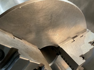
The limited pictures (I.e. your original post) it looks like the same 3J that I have (mine is the original chuck from new) - there is no brand on mine, just: S200ZD No 0692 79-

After quite a few years (and one incident where I had a piece come out - not a good day, I felt very stupid (because I did something dumb) - could have been much worse. Anyway, I had about 0.005” run out (worse as I got further out from the chuck) and bell mouth of the jaws. I made up a loading ring that tied into the inner bolt that secures the top jaws and recut the jaws - with a very good result.
 

Attachments

  • IMG_0577.jpeg
    IMG_0577.jpeg
    447 KB · Views: 13
I did already purchase the vfd. I'll just wire it directly to the motor for now
If you bought an offshore VFD as a 3HP for a 3HP motor, there is one setting that you should do before trying to turn the gearbox. The ratings are 'just enough', and with the excessive mass to start up of the gear train and chuck, you should set your motor ramp up speed to something long, like 10 seconds. This will minimize the strain on the VFD electronics, and help it to survive longer. I usually specify the next-size-up when going for a cheapie, such as a 5HP VFD for a 3HP motor.

One other thing you need to know before wiring it up. If the input is 1ph/3ph, then the VFD can only safely drive about 60% of it's rated HP. A 3HP VFD that has a3PH/1PG input can only drive a 2HP motor without excessive heating on the input electronics.

If it is a dedicated 1PH input the above paragraph is to be ignored.

Luckily, the way we hobbyists use our machines, there is a little 'wiggle room' - 10 second start helps, and not loading the motor with excessive cutting loads will help as well. The disconnected motor at idle will take about 10-15% of its rated current. Just turning the chuck can raise it to 50% on many lathes - mine is about 55%. So just idling the lathe at moderate speed can be getting close to the undesirable current range if you have a dual input VFD, so take baby steps so your VFD investment will be realized....
 
Back
Top