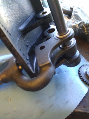
Greg's Logan 820 Restoration

That's a very cool accessory to have included when you buy a lathe. The nut should be a piece of cake with the proper taps. Metallurgy isn't my strong point...but I think the nut wants to be made from either cast iron or bronze. Not saying you couldn't make one out of brass, just don't know how it would wear. Back to the original post.....

Greg,
There's more than one way to skin a cat. Glad you got it straightened out. I'm kind of surprised that there wasn't enough wear in the holes to allow the shaft to slide through even with a little bit of twist in the casting. The pins you need to make shouldn't be any problem at all. I don't think there's any need to harden them. The gears that run on them have bushings IIRC. You should have a great machine when you get done.

Chuck
 
Hey;

Good deal on the handle. You're a brave man! Regarding hardening parts; never harden anything that will effect the life of an irreplaceable or difficult/expensive to replace part. Those precious parts should be the hardest things in the grouping. Make the easy to replace parts the softest.
 
Re: Greg's Logan 820 Restoration - still on the QCGB shift arms

It's been a few weeks since you last heard from me... Having successfully straightened out the warped shift arm, I decided to bore and bush the shift arms, as had been suggested. I had misgivings about tackling this enhancement, but finally decided it was worth a try, assuming I could get a good setup in my mini-mill.
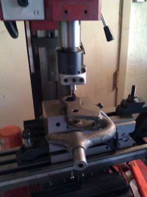
To improve the odds of success, I machined a support spacer and a centering jig/bore gauge. You can see them in this photo of my milling setup.
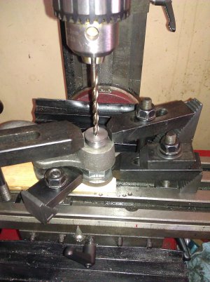
shift arm boring setup.jpg
The spacer was a nut, milled down to 0.492" thick, with a 7/8+" hole bored through. It is to prevent re-bending the arm under the clamping and boring forces and sits in the gap between the fork arms. You see it between the two lower clamp arms.
Between the two upper clamp arms, positioned for centering the quill is the jig, made from the head of a 3/4" bolt. Its bottom half is 3/4", to fit the existing holes in the casting and it has a tapped 1/4-20 hole down its center. In the photo, a drill bit being used for X-Y alignment before I switch to the boring head. The top half of the jig is 0.875" O.D. Flipping it over and screwing a bolt into the hole as a handle gives me a bore gauge to check the fit of my bronze bushings into the casting.
A thin piece of hardwood, with a cutout to improve the support, sits under the casting so I don't try to bore into the bed.
...

Given that I've ignored the "if it works, don't **** with it" warning, have I taken adequate precautions? I think so. Did I forget anything? I don't think I did.

How did it turn out? (Note: references to X and Y are as the casting is clamped in the mill in the above photo, i.e. X is the long dimension of the arm.)

Not very well! What went wrong? The first piece I did was the right side arm. The apparent root problem was that the boss on the bottom of the casting (the side against the wood ) was not quite perpendicular with the intended hole centerline. So while the boring may have been on center at the start, it was crooked in both x and y so that by the end of the bore, it was way off: 0.030" X and 0.094" Y. A trial fitting of the shift arm on the slider shaft in the gearbox showed this was crooked enough to interfere with the guide arm/guide slots and detent pin alignment. I'm not sure how badly it impacted the gear alignment; regardless it needed to be fixed. I will discuss that below.
On the second arm, given the mess I'd made on the first one, I bored one side, flipped it over, and did the other. Much better, but still not perfect. It should be close enough.

To fix the right arm, my plan was to machine some steel inserts, epoxy them into place, and rebore. With the crooked holes, I also had lost the "proper" center point. So I had to calculate the proper center, in X it was based on the pitch radii of the two gears. In Y, a line through the big hole center and the small hole center should be near the edge of the hole for the guide pin. To ensure proper Z-alignment this time, I put a rod thru the small holes and shimmed the casting until the rod was parallel with the quill. (Yes, the mill is in-tram.)

This fix didn't work, the epoxy (JB-Weld) didn't hold, and the insert broke loose during boring.

What do I try next? My remaining idea is drill and tap three holes radially around the approximate centerline, then use setscrews to manuever the bushing and casting into position so the gears properly mesh and the shaft is in alignment. Once I am satisfied, I will lock them in place with the JB Weld to fill the gaps.
If that doesn't work, maybe I go to a local machine shop and see what they can do.

Anyone got any other ideas? Or a spare right shift arm for sale? (None on eBay or at Logan)

Greg

shift arm boring setup.jpg
 
Greg,

Man, that's a bummer. You'll probably need to bore it out and press in a bushing.

Steve
 
Greg, I feel bad for mentioning that I did that to my lathe. I just clamped them in my mill vise and bored them with a boring head. How far oversize do you have the holes now? Is there still enough meat left in them to be bored straight and bushed with a thicker bushing then you initially planned? As a last resort you could braze it and build it back up. Also, there is a guy that always lists logan parts on chicago cl. I've bought from him before. He buys whole lathes and parts them out. It might be worth giving him a call and see if he has a handle. Heres one of his posts with his phone #.

http://chicago.craigslist.org/nwc/tls/4160906606.html

Chuck
 
Chuck,
Please don't feel bad. It was a good suggestion and it worked for you. I took a risk and failed. Not the first time. My mill vise wasn't big enough to securely hold the work, so I did the direct clamping, as shown in the picture. I'm afraid that I would have likely had the same problem, even with a vise, due to that off-square boss.
Right now the holes have been opened from 3/4" (for the shaft), to 7/8" (for the standard OD for a 3/4" ID bushing). But again, the problem is the holes are off-center. Yeah, there's enough "meat" to bore out to 1", or even more. Maybe if I had tried to braze the sleeves it would have gone better?
As you suggest, maybe I find or make some thicker bushings. I could plug it with a piece of 1" rod (bronze?) then rebore for the shaft. Now, the tricky problem is that I don't have an exact location of the original hole center line and I don't think that it is supposed to be exactly in the middle of the casting. Thus my plan for the setscrew-adjustable idea, at least to find the center by partial reassembly with shaft, gears, and the gearbox housing. Or, new idea: make a few of the 1" plug/bushings and drill them differently: 1) on-center, 2) .010 off-center, 3) .020 off-center... Then, in the trial-fitting process, try rotating the bushing for best alignment before locking into place.
I called your Craigslist buddy, he doesn't have anything at this time. He said to keep my eye on eBay, and to inquire on the Logan-specific Yahoo groups. I will do that as I proceed with my ideas.

Greg

Greg, I feel bad for mentioning that I did that to my lathe. I just clamped them in my mill vise and bored them with a boring head. How far oversize do you have the holes now? Is there still enough meat left in them to be bored straight and bushed with a thicker bushing then you initially planned? As a last resort you could braze it and build it back up. Also, there is a guy that always lists logan parts on chicago cl. I've bought from him before. He buys whole lathes and parts them out. It might be worth giving him a call and see if he has a handle. Heres one of his posts with his phone #.

http://chicago.craigslist.org/nwc/tls/4160906606.html

Chuck
 
Re: Greg's Logan 820 Restoration - boring the shift arm - 3rd try

As I said a few days ago, one tricky part is now trying to find the proper center. This should do:
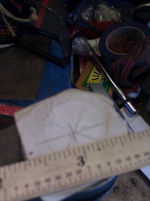
shift arm hole locating.jpg
First, I stuck a paper label over the off-centered .875" hole. This is on the thin side of the fork. I am going to assume the hole should be in the center of the casting's boss, so I used a center square to find the center. The center to center distance between the holes will be critical for proper gear mesh, so I struck an arc at 1 15/16" from the small hole. (The steel rule's 1" mark is at that center.)

The other tricky part is secure, square work-holding. I don't have a good, big milling vise, which is why my first tries I fastened the work directly to the table. I spent an hour or two yesterday trying to use a cheap 6" drill press vise. But I stuck a 6" pin into the small hole as a guide to get the work properly vertical (which didn't happen the first time). Try as I might, I couldn't get it shimmed plumb.

So today, I tried my 3" sine vise.
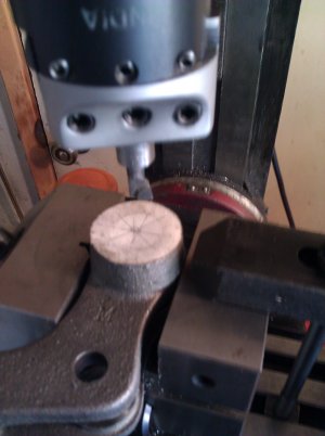
shift arm boring 3rd try.jpg
In the y-axis,it was fine as is. But the guide pin (not shown in this photo) showed .030" of x-axis skew over a 3" distance. If you look carefully, you can see the sine table is slightly cracked open to get everything in alignment.
I'm now in the middle of boring the thin side at the new, true(?) center, planning for about 1.1" diameter. Why this size? Because of the uncertainty in hole positioning, I plan to make some test sleeves with various offsets if needed. I was thinking of making the test sleeves from hardwood, but found something better: 1/2" double female PVC pipe couplers. They are 1.1" OD, .840 ID, and 1.875 long. I will bore them to .875 for my 3/4 ID bronze Oilite bushings, with varying degrees of eccentricity in the boring if needed.
Once I find the proper offset, I'll make the final one from a scrap piece of 1.5" 10L14 steel rod.

That's the plan for this week's effort.
Greg

shift arm hole locating.jpg shift arm boring 3rd try.jpg
 
Sounds like you have a plan. Are you planning on putting a bushing inside of the 10L14 or just running that and oiling it frequently?

Chuck
 
Re: Greg's Logan 820 Restoration - shift arm progress

Yes Chuck, I still plan to insert Oilite bushings. Things are going well.
I bored the thick side of the shift arm fork, using the setup shown in my last posting. It seemed to go well.
Then I flipped it over, found the center by the similar method as before, and bored the thin side...
shift arm boring other side.jpg
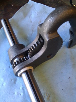
This too went well, so I now had 1.1" holes where I need a 3/4" hole. I made the temporary test collars out of 1/2" PVC pipe couplers, bored out to 7/8" for the Oilite bushings. The first set I bored on-center. I would make off-center ones as needed. But first a test fitting, checking for gear mesh and for alignment with the QCGB body casting's pin holes A-F.
shift arm pvc gear mesh.jpgshift arm pvc collar1.jpg
Both the gear mesh and the pin-to-hole alignment were great. Just to be sure, I made a second set of PVC test collars, boring off-set by 0.010". I then retried the above checks, rotating the eccentric collars into multiple positions (i.e. 0, 90, 180, and 270 degree alignments.) It didn't seem to make much difference anywhere. So I decided to go with the zero-offset.
I was going to use an on-hand piece of 12L14 steel, but it would be a shame to "waste" so much of it. (Turning down from 1.5" to 1.1, then boring out to .875) - more swarf than part!
At the local scrap yard, I got a 3-foot piece of 1.25" POS (plain ol' steel). I've sliced off 1-inch and 1/2" pieces and will probably turn and bore them tomorrow.
Then, one final test fitting, disassemble again, paint, and final reassembly.

Greg

shift arm boring other side.jpg shift arm pvc gear mesh.jpg shift arm pvc collar1.jpg
 
Back
Top