Greg's Logan 820 Restoration

Thanks again Chuck! I guess I will see today as I put it together. I have plenty of things to use as the dummy shaft. An idea to help line up all those keyways: on each gear, I think it will help to use some Dykem to mark the gear tooth that lines up with the keyway. [Once I get the gears all clean and shining.)
Greg

Greg, You'll understand what I mean about frustration when you start trying to line up all of the keyed gears to get the shaft through. You might get lucky and they just fall into place but the dowel makes it easy. I guess your handles must be all wallowed out like most of them I've seen. It's not as hard to set them up for boring as it appears. I have to check and see if I have any pics. I think I just held them in my vise. If you decide to bush the handles, don't try to get too close on your fit or you will be pulling the shaft back out and polishing it down to make your handles slide easier....been there done that.:))

Chuck
 
Re: Greg's Logan 820 Restoration - QCGB Shafts Pt 1

While waiting on some replacement parts from Logan Actuator (bushings and pins), I’ve begun making the replacements for the worn shafts identified during the teardown, as detailed in the recent posts. First on the list: the slider shaft for the selector arms. First, I needed to reassemble the QCGB and apron/saddle so I could use the lathe to make the new shafts.

Reassembling the gearbox was not too difficult, except that somewhere in my efforts, the detent pin on the right shift arm got bent. I must have force-fit something when reassembling the shift arms onto the slider shaft (and getting the gears engaged with the cluster gears. I don't think that pin will come out the front, will it? I will have to work on this when I replace the slider shaft, may need to make a new pin. By the way, the order I put the parts together was input shaft/gears, main shaft/cluster gears, slider shaft/gears/arms, and finally, the leadscrew. The slider/shift arms was the hardest part.

You may remember that a few weeks ago, in the apron/saddle restoration, I had to put the lathe back together so that I could make a new shaft for the apron handwheel. Then I had to pull the apron off, split it open, replace the shaft, and reassemble again. But I never put the apron back on the saddle to test it, instead I dove into the QCGB overhaul.

With
everything back together, I quickly found that the handwheel didn’t work! The power feeds were okay, but not the manual… Tore it apart again and quickly saw that I’d put the gear on backwards. Doh! Turned the gear around, redid the gasket maker again (third time) and now all is well.

Then, my raw material for the shaft was going to be a chunk of ¾” rod from Home Depot. It may have been a nominal ¾”, but the micrometer said it was a bit too small. So I got a yard of ¾” drill rod; my finished, polished shaft is 0.7500” and fits very nicely into the replacement bushings.

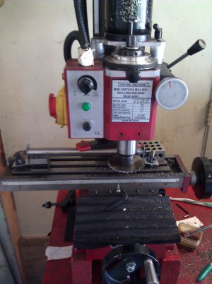
In an earlier posting in this thread (QCGB Teardown 1), I discussed how my QCGB slider shaft was not in accordance with the parts catalog, since it was pinned into place, rather than a collar and bolt. I decided that I would follow the parts catalog on this. Thus I made the new shaft about 0.5" longer than the incumbent one, and drilled/tapped each end for 1/4NC20 bolts. This was partially for operational purposes, and also to help mount the shaft on the mill for cutting the ⅛” keyslot. See the pictures below for my machining setup.


slitting the slider shaft2.jpg
This was the first time I've used my slitting saw, and unfortunately, the blade's hole is a few thou bigger than the arbor's diameter. The resulting run-out would cause one or two teeth to do most of the cutting. Not good. I mitigated the run-out with a paper shim, but it was still a problem.

So I cut the 0.118 deep keyslot about .010" (or less) at a time. Let's see: call it 20 passes x 8 inches x 16 turns/inch = approximately 2560 turns on the X-handwheel. While I was cranking back and forth, (at about maybe 30 rpm) I was thinking how nice a motorized feed would be. Maybe a future project? But certainly not in time for the next QCGB piece, the "main" shaft; it needs 3.5" of 3/16" wide, 1/8" deep keyslot. I will start on it today.

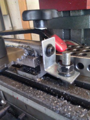
And here is a close-up on how I held the shaft, using the threaded end holes for mounting brackets, while cutting the keyslot.
slitting the slider shaft1.jpg
Bye for now,
Greg

slitting the slider shaft2.jpg slitting the slider shaft1.jpg
 
Wow...as Ricky Bobby's kids would say, "You made that shaft your b****". I've made those shafts a couple of times, but I just hold the shaft in the vice and cut it with an endmill. The slot turned out nice and uniform. The bushings your waiting on could probably be found at your local hardware store. They would probably be about the same price as Logan charges. I order them from Motion Industries. Unless it's one of the odd sized ones that they don't stock in their warehouse locally, they usually cost .50 - 1.00 each. The nice thing about buying them from Logan is that you don't have to remove and measure each one....you just buy the bushing kit. Sounds like your moving right along on the project. You make me want to find another Logan to work on. Keep the pics coming.

Chuck
 
Re: Greg's Logan 820 Restoration - QCGB Shafts Pt 2

New shafts ready
Okay, I've now made the two replacement shafts for the gearbox.
As shown in my last posting, on the slider shaft, I used a slitting saw for the first time, for the long, 1/8" wide keyslot. But as I said before, it was many shallow passes; slow going, but with good results.
Then last week, I made the replacement "main" shaft. This is the one with three diameters (3/4", 5/8", and 9/16") and a 3/16" wide x 1/8" deep keyslot. (The shaft with the fourteen gears on it.) I tried to do this with a 3/16 slitting saw, but it was even slower than the previous slitting task. After many passes and only about 0.050" penetration, I decided that my X2 mini-mill lacked the necessary low-speed torque (or rigidity?) to do this job right, at least in steel stock.
So I followed Chuck K's advice, rotated the in-process slot to the 12 o'clock position and quickly finished the slot with a 4-flute end mill. Bonus: this also left the work aligned to drill the 0.062 in the bottom of the slot, for the tiny pin on the key.
  • Somewhere I'd read that one should use a 2-flute end mill for slitting, because 4-flutes didn't do a nice job. And, one shouldn't try to cut both side of the slot at once. Oh well; I took shallow cuts (0.010 - 0.015 range) and it worked fine. I don't own any 2-flutes, maybe I should?

Gearbox Damage?
While waiting for my QCBG bushings to show up, I decided to make some replacement fillister-head screws for ones with screwed-up screwdriver slots. First up, the 1/4-20 NC x 1.5" screws for the front gibs.
I had mentioned that somehow, during gearbox reassemble, I forced something and bent the right shift arm detent pin. Apparently I damaged more than just that pin. When I set up to single-point thread this screw I found it very difficult to get the right-hand shift arm into the 20-TPI position. But, very stupidly, I managed to force it into gear. And, when I turned the lathe on, in slow speed, back-gear mode, it basically stalled. (aka crashed?) I haven't yet pulled the gearbox, but turning the gears by hand and trying to engage the right shifter into all but the rightmost one or two positions, I can feel something is now eccentric. I hope it's a bent main shaft and not damaged gear teeth!
This afternoon or tomorrow I will pull the QCGB and see what I have done.

This is why my wife doesn't let me work on her brakes anymore!
Your ham-fisted, would-be machinist,
Greg


"Give me a hammer."
"What size?"
"It doesn't matter... I'm gonna use it as a hammer."
 
I can't imagine what you could have damaged. When you say "detent pin" I'm assuming you mean the spring loaded pin that holds the lever in position. I suppose it's possible that it's allowing the the gear to be pushed in too tight. If there's no broken teeth your in good shape.

Chuck
 
Re: Greg's Logan 820 Restoration - Fixing the QCGB

I pulled the gearbox to see what I had done wrong on my previous reassembly, and what damage has been done. As I had said before, the right shift arm would not properly engage into the gears (except for the rightmost one.) And the tip of the spring-loaded detent pin was bent.
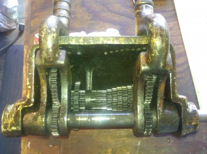
For reference purposes, here again is the inside of the gearbox from the bottom, prior to my initial disassembly.
qcgb, bottom view, before.jpg
You can see that the left and right shift arm assemblies are mirror-images of each other, including the two gears captive on each arm. My mistake was that on the right arm, I put the two gears on backwards, so that the spacer was toward the center rather than to the right. I should have referred to the picture! This caused the gears to be out of position by 1/4" to the right, where they would try to engage the next gear over on the main shaft. And since next gear to the right is a larger gear, no wonder the arm would not come up enough to engage the pin.

Luckily, no catastrophic damage, all the teeth are still good. I thought I may have bent the main shaft or the slider shaft, but now I don't think so. I don't know what was making it feel out-of-round when I was trying to force the right shifter into place. Best as I can tell at the moment, the main shaft is not bent, but I haven't removed it yet.
I straightened the detent pin as best I could, and will at least make some accurate measurements of its dimensions so I can make a replacement. I might just go ahead and do that without the gearbox. We'll see.

My home-made slider shaft was almost ready-to-go. But it seems my 0.125 slitting saw only cuts about 0.118 slot. I had been obsessing on the slot depth and never double checked that width. For the keyed gear to fit, I needed to widen the slot. So I ran a 1/8" end mill through it and also had to deburr the slot edges. Now it's good.

Another self-inflicted wound: I slightly distorted the right shift arm casting when using my vise in either removing or replacing the gear axle pin on the shift assembly. It's not off by much, after all, the shaft and the axle do go thru, but the gear on the axle doesn't spin as readily as the one on the left shift arm (cause it's pinched by the casting), and the new slider shaft doesn't nicely slide through both sides of the casting. Those pins were really, really tight, and although I was aware of the potential, and tried to adequately support the work with makeshift spacers, something now is not quite right.
I'm not yet sure how I am going to fix it, but the ends of the fork need to come apart to get thing back in parallel. Possibilities include
  • Maybe brute force bending the gap open (with a crowbar?),
  • Maybe just running a reamer through the shaft and axle holes,
  • Maybe I can make a tiny nut-and-screw jack, but it has to fit into a 1/2" gap.
  • Maybe I can use my gear puller/wheel puller as a pusher. This I can try pretty quickly.
  • Maybe I can support the top fork in my 1 ton arbor press and press against the bottom fork.
Anyone got some other ideas?

I am yet to check how well my replacement main shaft is going to fit. And after I fix the fork, then I will clean, repaint and reassemble.

Greg

qcgb, bottom view, before.jpg
 
Greg, It's been a while since I've had one of those boxes apart, but I seem to recall that the pins that the gears ride on are knurled. If you press them out the correct way, they come out fairly easy....not so much the other way. I'm kind of surprised that the shift arm bent rather than cracking. I would be reluctant to try bending it back. I think I would relieve it a little with a file. Usually the holes the main shaft slides through are egg shaped and loose. If you bore and bush the holes you should be able to take care of your alignment problem in the process. Good luck

Chuck
 
Oh My...

I'm with Chuck. I wouldn't chance trying to bend a cast part. Only as a last resort, anyhow. I like the profile and ream idea better.
 
Re: Greg's Logan 820 Restoration - fixing QCGB shift arm

Chuck K and Redlineman,
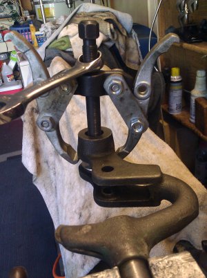
Thanks for the ideas and the warnings about bending cast iron, I hadn't thought about the shift arm breaking. On the other hand, given that I distorted it rather than breaking it suggests that I can un-distort it safely. Would that be called "torting?" :)) I only needed to spread the arms 0.005", so I tried the gear puller idea I mentioned. Here's the idea in execution...
shift arm spreading.jpg
The gear puller is pulling on one side of the shift arm fork, and pushing against a pair of fender washers sitting on the other fork. Apparently the cast iron is adequately ductile to withstand this treatment, it would flex open several thousandths, but then flex back closed, loosing most of the improvement. So I repeated a few times, working up to a 0.012 flex that when relaxed, had adequately restored the gap for the gears.
But the big holes were still not quite adequately aligned. I secured the fork in the vise, placed a piece of 3/4" rod in the hole and with the 3 feet of leverage, easily tweaked the alignment for the shaft and pin.

Chuck, you're right about the knurled ends on those pins. Luckily, when I first drove them out, I did it the right way and didn't push the knurls through the gear bushing and other end. The pins are slightly worn, so I intend to replace them. But it turns out the "replacement" pins from Logan Actuator are the wrong size (3/8" rather than 7/16"). I'm waiting to hear back from them on whether they have the parts or not. But I may just make my own from drill rod. If so, I think I will harden these pieces.

I'm now in the process of replacing bushings on the gearbox housing and on several gears, repainting the gearbox casting and the shift arms.

Greg

shift arm spreading.jpg
 
Back
Top