Has anyone installed Clough42's electronic leadscrew on a PM machine?

Can you post photos or more details on mounting conditions please?
Of course you have to watch all of Clough42's videos on the ELS.
Clough42 Github link.

image8.jpeg

Control Cabinet
image10.jpeg

image11.jpeg

image9.jpeg


image7.jpeg

Mounting position
image6.jpeg

Servo used from AliExpress approximately $175 delivered. Looks like it's increased in price $15 since I purchased one. Delivered in 2 weeks.
image4.jpeg

Made bracket out of .200" aluminum. Drilled and tapped lower base of lathe. Pretty rigid.
image1.jpeg

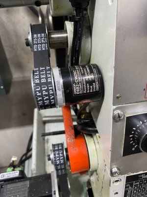
Encoder mounted on approximately 1.5"x0.20" aluminum flat bar. Made a bushing so removing 120/127 tooth gear and utilizing same bolt.
Timing gears are all 40 teeth. 2 on the lathe are 18mm ID with keyways from Ebay, 1 on encoder is 6mm ID, 1 on servo is 14mm ID with keyway. They all had hubs that were drilled and tapped for set screw but I turned the hub off and drilled and tapped the center for a set screw. Belts from Ebay, 1-91 tooth (273mm length), 1-125 tooth (375mm length).
image0.jpeg


image5.jpeg


Only modification was a notch cut in bottom lip of cover.
 

Attachments

  • image2.jpeg
    image2.jpeg
    51.9 KB · Views: 197
Last edited:
I recently finished installing one on my PM1030v. I used the integrated servo James did a review on a couple of months ago, primarily because it eliminated the need for a separate stepper driver. Because the PM has a separate feed drive from the leadscrew I'm using a slightly different approach to the gear reduction between the servo and the leadscrew. Like James I'm using a 3:1 gear reduction belt drive from the servo to the gearbox on the lathe. When threading I use the 2:1 position on the lathe gearbox (same as James) for an overall reduction of 6:1. However the power feed in the PM1030 effectively provides an additional 10:3 gear reduction in the saddle, which I felt was too much gear reduction, so I have mine programmed to be used with the gearbox in the 1:2 position providing an overall gear reduction of 5:1 in feed mode. I integrated everything except the servo power supply in the lathe itself. The servo is mounted inside the lathe bed casting (this was a tight fit), and the electronics are mounted in the electric enclosure on the back of the lathe. The encoder and servo mounts are 3d printed parts. The power supply is mounted to the bottom of the bench top the lathe sits on.

-Pete

A couple of pictures....View attachment 378143View attachment 378145
@paradox_pete Im getting ready to add this to my PM1030V and had 2 questions:

1) you said "I have mine programmed to be used with the gearbox in the 1:2 position providing an overall gear reduction of 5:1 in feed mode" can you provide a bit more detail on how you did this, i dont have the components yet (all on order) but was wondering how intuitive this part is?

2) "The encoder and servo mounts are 3d printed parts" - did you model these yourself, where can I find them?

Thanks in advance!
Hi Dakegg,

Regarding the programming part, that is done in the configuration file that is part of the process of programming the controller board. The relevant part of the configuration for my setup looks like this:
//================================================================================
// STEPPER/SERVO
//
// Define the number of steps and microsteps for your stepper motor, the pin
// polarity of the driver, and whether to use additional features, like servo
// alarm feedback.
//
// NOTE: If you are using a servo drive with something other than a 1:1 drive
// ratio, you can use the STEPPER_MICROSTEPS to compensate. For example, if you
// have a servo configured for 1000 steps/revolution and it drives the leadscrew
// through a 3:1 reduction, you can set STEPPER_RESOLUTION to 1000 and
// STEPPER_MICROSTEPS to 3.
//================================================================================

// Steps and microsteps
#define STEPPER_MICROSTEPS 6
#define STEPPER_RESOLUTION 500

// Separate step and microstep settings for feed rates. Redefine these if your
// lathe has a separate feed drive train with a different ratio.
#define STEPPER_MICROSTEPS_FEED 10
#define STEPPER_RESOLUTION_FEED STEPPER_RESOLUTION

I did model the mounts myself, I've attached the STL's, and the previously posted pictures might help see how I've arranged things. The servo was a VERY close fit in the lathe bed. If there is any variation in castings it might not fit. I had to attach the wires after fiddling the servo into place, reaching in from the chuck side. I also added shields to prevent chips getting in there....

Integrating the display where the factory tach display was did require enlarging that hole, but I thin that is the only physical change I made to the lathe.

I hope that helps.

-Pete
 

Attachments

  • ELS_Encoder_Mount_2-Body.stl
    2.6 MB · Views: 153
So apparently the servo mount STL is too big to attach here. I've uploaded it to Thingiverse.

Also, you would want to print it with the flat side up, of course. It appears to load upside down.....(no doubt an artifact of my modeling approach.)
 
Last edited:
That @clough42 ELS is a real Godsend on my Grizzly G4000

Did you make any posts on doing your conversion? I have an Enco 9x20 (near identical to the G4000) that came with no change gears, so I've been thinking about adding an ELS. Electronics are not my strong suit which is holding back my enthusiasm for the project.
 
Absolutely, I documented it here:
 
Thanks so much! Clough42 panel and board are on the way, so is the servo, encoder and misc parts, just need to wait on the TI board. Apparently some time around Aug it will be available again. In the meantime I'm mounting a DRO on the lathe, so that'll keep me busy a bit longer.

That thingiverse link is not working.. I was able to pull the encoder mount but the servo mount is a dead link right now...
 
I did this conversion on my lathe a few months ago, and it was the best thing I have ever done to my lathe. Now instead of grabbing a tap or die, I push a couple of buttons and thread on my lathe.
Steve
 
I recently finished installing one on my PM1030v. I used the integrated servo James did a review on a couple of months ago, primarily because it eliminated the need for a separate stepper driver. Because the PM has a separate feed drive from the leadscrew I'm using a slightly different approach to the gear reduction between the servo and the leadscrew. Like James I'm using a 3:1 gear reduction belt drive from the servo to the gearbox on the lathe. When threading I use the 2:1 position on the lathe gearbox (same as James) for an overall reduction of 6:1. However the power feed in the PM1030 effectively provides an additional 10:3 gear reduction in the saddle, which I felt was too much gear reduction, so I have mine programmed to be used with the gearbox in the 1:2 position providing an overall gear reduction of 5:1 in feed mode. I integrated everything except the servo power supply in the lathe itself. The servo is mounted inside the lathe bed casting (this was a tight fit), and the electronics are mounted in the electric enclosure on the back of the lathe. The encoder and servo mounts are 3d printed parts. The power supply is mounted to the bottom of the bench top the lathe sits on.

-Pete

A couple of pictures....View attachment 378143View attachment 378145
Pete- Please post a list of the components that you used to make this modification. I would like to the same modification to my PM 1022.
Thanks very much, Mondshine
 
Back
Top