

-
Welcome back Guest! Did you know you can mentor other members here at H-M? If not, please check out our Relaunch of Hobby Machinist Mentoring Program!
You are using an out of date browser. It may not display this or other websites correctly.
You should upgrade or use an alternative browser.
You should upgrade or use an alternative browser.
Help with Clausing 4903 Magnetic Starter
- Thread starter DNORM25
- Start date
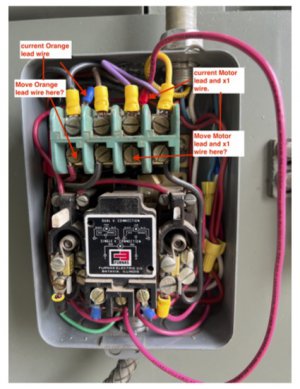
Looks like something changed between the first and last pictures. If the heavy red wire going outside the box in the first pic is a motor lead it should land on T2 which is just below the purple L2 wire on the top of the contactor. You can see the T2 marking on the bluish green insulator.
0 volts between v and w. That's with the drum switch in forward or reverse.If you're comfortable with it check for voltage between V and W with the drum switch on. Wear face protection and heavy gloves.
The red wire to the left of the left reset is on a terminal labeled x2. Its other end is conected to t2 which when powered has 120 volts. Does this wire feed power to the coil? should it be tapped into a terminal that feeds 240v?
Please bare with me, i'm trying to wrap my head around this and I want to make sure I am understanding correctly. The Orange wire, motor lead and x2 wire need to be attached as shown in the included pictureI think I see the issue. The orange #3 wire is landed on #2 terminal. #3 terminal is located below #2 terminal. You can see the 3 marking on the bluish green insulator.
Attachments
Okay change the leads, but made no difference. Contractor doesn’t pull in and there is no voltage between V and WYes, exactly. Always good to be sure.
- Joined
- Apr 30, 2015
- Messages
- 11,309
Don't know if it's an issue but the leftmost finger looks bent more than the others- Check and make sure the
contact fingers are working normally and none of the "spiders" have come loose from the shaft
Otherwise the switch wiring looks fine- thank goodness Clausing used color coded wires

contact fingers are working normally and none of the "spiders" have come loose from the shaft
Otherwise the switch wiring looks fine- thank goodness Clausing used color coded wires
Will do! Thanks for the replyDon't know if it's an issue but the leftmost finger looks bent more than the others- Check and make sure the
contact fingers are working normally and none of the "spiders" have come loose from the shaft
Otherwise the switch wiring looks fine- thank goodness Clausing used color coded wires
View attachment 467274
Sorry for the delay getting back. Let's try some checks to figure out where we're losing the voltage. With power on and drum switch on check between coil wire V and red wire X2 on the left overload. If you have 240V we're pretty sure it's wired correctly. Then move probe off X2 and on to wire that goes between the overloads. If you lost voltage then the left overload is tripped or bad. If you still have 240V move the probe to the reed wire on the right of the right overload (should be the wire that goes down to coil wire W). If you lost the 240V then the right overload is tripped or bad. If the right overload is the issue, with the power off, you can try to reset it by pushing in the broken plunger with a small screw driver or punch. It can also be stuck too far in when it was broken so you can try tapping it with whatever tool quickly to see if it will bounce out. Also if you could get a few pics of different angles on how it's wired now.