Help with Clausing 4903 Magnetic Starter

Sorry for the delay getting back. Let's try some checks to figure out where we're losing the voltage. With power on and drum switch on check between coil wire V and red wire X2 on the left overload. If you have 240V we're pretty sure it's wired correctly. Then move probe off X2 and on to wire that goes between the overloads. If you lost voltage then the left overload is tripped or bad. If you still have 240V move the probe to the reed wire on the right of the right overload (should be the wire that goes down to coil wire W). If you lost the 240V then the right overload is tripped or bad. If the right overload is the issue, with the power off, you can try to reset it by pushing in the broken plunger with a small screw driver or punch. It can also be stuck too far in when it was broken so you can try tapping it with whatever tool quickly to see if it will bounce out. Also if you could get a few pics of different angles on how it's wired now.
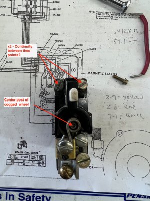
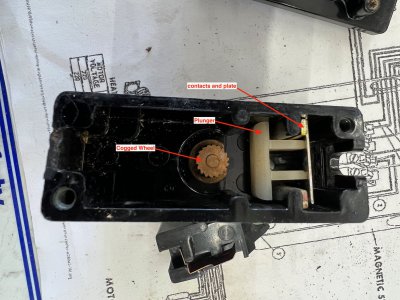
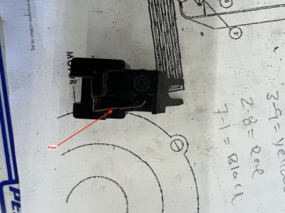
Could you explain to me how the overloads work?. I was not getting power to the jumpers on the top side of the overloads, so i took them apart to see how they work. It seems the x2 wire is one side of a contact and theres a metal plate that bridges each side of the contact to feed power across to the other thermal overload top section via jumper wires. Below that and separated by a plastic plunger, the metal cogged wheel that is attached to a post that goes in the middle of the coiled wire (reed wire?) between the terminals Of the overload. Over the cogged wheel is a plastic component with a copper pawl that contacts the cogged wheel. I assume that when the thermal overload melts, the spring pressure behind this part allows this pawl to turn the cogged wheel and push the plunger to disengage the upper contact plate stopping power from transferring from x2 to the the other side and thus the other overload.

Assuming i understand this correctly, if the overload is good there should be continuity between x2 and the screw tap to its right. The lower terminal should have continuity between all of the taps above and below the coiled wire. Internally i see no relationship between the upper x2 tap and the lower wire attachment, only the spring pressure to push the plunger and separate the upper x2 contact points if the coiled spring were to melt. Sorry if this is obvious or completely off base. I’m trying to understand the concept. Upon reassembly, i assume after the springs are inserted, i should pull the pawl back to allow the upper contact plate to bridge the x2 and jumper terminal?
 

Attachments

  • IMG_0383.jpeg
    IMG_0383.jpeg
    362 KB · Views: 3
  • IMG_0385.jpeg
    IMG_0385.jpeg
    478.3 KB · Views: 3
  • IMG_0386.jpeg
    IMG_0386.jpeg
    393.4 KB · Views: 3
The coiled wire is called a heater and has a slight resistance. The motor current runs through the coil. The left on is T1 and the right T3. As the motor becomes loaded down more current flows through the coil and to the motor. This creates heat in proportion to the current. When the motor is overloaded the heat is at a level where it trips the overload block which opens the contacts you found at the top. I believe on this type of overload there is an easily melted metal below the cogged wheel that when melted allows the wheel to spin so the pawl can't hold the contacts closed. When cooled you should be able to push the white reset plunger and contacts are closed again. So you have 2 circuits in the block, the control circuit through the upper contacts and and the motor circuit through the heater coil. Also, the heater coil needs to be sized to the motor full load amp rating.
 
You can test that the o/l (overload) is the issue with you contactor not pulling in by reassembling everything then putting a temporary wire between the far left o/l contact terminal (x2?) and the far right contact terminal. To be clear jumpering across the red wires not the heater coil terminals. Disconnect the T1 T2 and T3 wires to the motor so it's out of the picture. Try to start it and if the contactor pulls in you know the problem is in the o/l. You can then jumper out the o/l one at a time to prove which one is not resetting.
 
The coiled wire is called a heater and has a slight resistance. The motor current runs through the coil. The left on is T1 and the right T3. As the motor becomes loaded down more current flows through the coil and to the motor. This creates heat in proportion to the current. When the motor is overloaded the heat is at a level where it trips the overload block which opens the contacts you found at the top. I believe on this type of overload there is an easily melted metal below the cogged wheel that when melted allows the wheel to spin so the pawl can't hold the contacts closed. When cooled you should be able to push the white reset plunger and contacts are closed again. So you have 2 circuits in the block, the control circuit through the upper contacts and and the motor circuit through the heater coil. Also, the heater coil needs to be sized to the motor full load amp rating.
Got it! so the upper control circuit should be closed If not tripped. The lower circuit feeds the upper termanal block via wire jumper. If overload occurs the low melting alloy melts and spring pressure pushes the upper terminal plate, opening the contact and interrupts supply voltage to the coil. thus releasing the electro magnet and opening the lower contacts of the terminal block.

i checked the voltage between x2 and V. It only reads .2v. Between V and ground and W and ground i get 220v each, but nothing between V and W.
Not sure if this is relevant, but I am running a rotary phase converter, is it possible that the wild leg of the converter is causing an issue and should be applied specificlly? Right now this leg, which reads 219 volts passes directly to the drum switch, the other two legs, which read 121.8 volts each, connect to the drum switch, and to #2 on the terminal block.
 
You got it. I don't know rotary converters but have heard about wild leg issues. Do the jumper check that I listed above and we can narrow it down. As far as reading V and W terminals to ground you introduce variables into the circuit. Basically you can read the voltage through the contactor coil that is on one terminal to the other terminal if that makes sense.
 
You can test that the o/l (overload) is the issue with you contactor not pulling in by reassembling everything then putting a temporary wire between the far left o/l contact terminal (x2?) and the far right contact terminal. To be clear jumpering across the red wires not the heater coil terminals. Disconnect the T1 T2 and T3 wires to the motor so it's out of the picture. Try to start it and if the contactor pulls in you know the problem is in the o/l. You can then jumper out the o/l one at a time to prove which one is not resetting.
There is continuity between x2 and the termination end of the red jumpers on the far left of the left o/l, so i assume that means the upper circuit is closed and the o/l’s are okay,
 
You got it. I don't know rotary converters but have heard about wild leg issues. Do the jumper check that I listed above and we can narrow it down. As far as reading V and W terminals to ground you introduce variables into the circuit. Basically you can read the voltage through the contactor coil that is on one terminal to the other terminal if that makes sense.
Meaning the contact coil taps V and W?. With power and the drum switch in forward there is no measurable voltage between them.
 
If I understand you circuit you should be able to read between V and L2 and have 240V. That tells you the drum switch is trying to pull in the the contactor. Then read between W and L2 and 240V means your coil is probably good. Then read from V to both sides of the left o/l. If you have 240V on one side but not the other the o/l contact is open and is an issue. If that was good, repeat for the other o/l.
 
Meaning the contact coil taps V and W?. With power and the drum switch in forward there is no measurable voltage between them.
With the coil I'm saying if you read between V or W and ground you could be reading the same 120V on both sides of the coil.
 
There is continuity between x2 and the termination end of the red jumpers on the far left of the left o/l, so i assume that means the upper circuit is closed and the o/l’s are okay,
Didn't see this post. Did you try it?
 
Back
Top