
If the wild leg might be an issue I think you could switch it to the L3 terminal and that would take it out of the contactor control circuit.Got it! so the upper control circuit should be closed If not tripped. The lower circuit feeds the upper termanal block via wire jumper. If overload occurs the low melting alloy melts and spring pressure pushes the upper terminal plate, opening the contact and interrupts supply voltage to the coil. thus releasing the electro magnet and opening the lower contacts of the terminal block.
i checked the voltage between x2 and V. It only reads .2v. Between V and ground and W and ground i get 220v each, but nothing between V and W.
Not sure if this is relevant, but I am running a rotary phase converter, is it possible that the wild leg of the converter is causing an issue and should be applied specificlly? Right now this leg, which reads 219 volts passes directly to the drum switch, the other two legs, which read 121.8 volts each, connect to the drum switch, and to #2 on the terminal block.

-
Welcome back Guest! Did you know you can mentor other members here at H-M? If not, please check out our Relaunch of Hobby Machinist Mentoring Program!
You are using an out of date browser. It may not display this or other websites correctly.
You should upgrade or use an alternative browser.
You should upgrade or use an alternative browser.
Help with Clausing 4903 Magnetic Starter
- Thread starter DNORM25
- Start date
Bear with me because I’m trying to follow.If the wild leg might be an issue I think you could switch it to the L3 terminal and that would take it out of the contactor control circuit.
V to L2 = .21V
W to L2 = .21V
V to X2 (top side of left o/l) = .22V,
V to T1 (bottom of left o/l) = 200v
W to X2 (top of right o/l) via jumpers = .21V,
W to T3 (bottom of right o/l) = 200v
Did the T2 red motor wire get moved down to the T2 terminal just below L2? Just to be sure, the T leads should be the wires going to the motor and the L wires should be the wires coming from the drum switch right? Does the #3 orange wire to L2 on top of the contactor have 240V? Does the #3 orange wire to L3 on top of the contactor have 240V?Bear with me because I’m trying to follow.
V to L2 = .21V
W to L2 = .21V
V to X2 (top side of left o/l) = .22V,
V to T1 (bottom of left o/l) = 200v
W to X2 (top of right o/l) via jumpers = .21V,
W to T3 (bottom of right o/l) = 200v
Yes they were moved. #3 to L2 = .21 v, #3 to L3 = 250 vDid the T2 red motor wire get moved down to the T2 terminal just below L2? Just to be sure, the T leads should be the wires going to the motor and the L wires should be the wires coming from the drum switch right? Does the #3 orange wire to L2 on top of the contactor have 240V? Does the #3 orange wire to L3 on top of the contactor have 240V?
What is #3 to L1?Yes they were moved. #3 to L2 = .21 v, #3 to L3 = 250 v
250v.What is #3 to L1?
so i connected the coil directly to 220 and the coil pulls in so it’s good.
just curious, tap V from the coil which ties in to #3 where the orange wire is located, when tested to ground reads 120v. tap W which ties to the upper circuit of the left o/l. is fed from the purple wire that comes from the drum switch and also reads 120. Why would i not read 240 across V and W? It actually reads next to nothing, Am i reading the same 120v from the same source?
If i look at the drum switch the the orange wire contacts engage in forward and the purple wire contacts engage in reverse. They never engage at the same time, meaning the coil is only getting 120v. I Think.
Yes, you're reading the same 120V because it goes through the coil. The pictures you took of the drum switch looks like it's in either forward or reverse. I think the first moveable contact closest to the conduit end should be in contact with the black to the orange wires. Can you take a picture of the drum switch in the off position?250v.
so i connected the coil directly to 220 and the coil pulls in so it’s good.
just curious, tap V from the coil which ties in to #3 where the orange wire is located, when tested to ground reads 120v. tap W which ties to the upper circuit of the left o/l. is fed from the purple wire that comes from the drum switch and also reads 120. Why would i not read 240 across V and W? It actually reads next to nothing, Am i reading the same 120v from the same source?
If i look at the drum switch the the orange wire contacts engage in forward and the purple wire contacts engage in reverse. They never engage at the same time, meaning the coil is only getting 120v. I Think.
The previous switch pictures were in the forward position.Yes, you're reading the same 120V because it goes through the coil. The pictures you took of the drum switch looks like it's in either forward or reverse. I think the first moveable contact closest to the conduit end should be in contact with the black to the orange wires. Can you take a picture of the drum switch in the off position?
Just an observation, if the orange wire were attached to the additional screw behind the black wire on terminal 2 and not below on terminal #3. Wouldn’t that effectively function as though black was bridging to orange at the switch even though its taking place in the starter enclosure? The feed to X2 is wired this way but from the post behind the purple wite on L2. There is no way for black to bridge to orange that i can see At the switch without re wiring it. The current wiring positions match with the clausing drawing posted previously, so if the documentation is correct the current switch wiring should be as well.
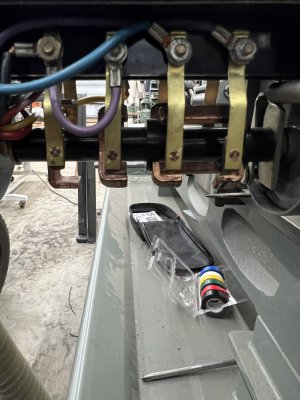
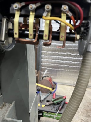
below are pictures in the off position.
thanks again for taking the time. I truly appreciate it.
Attachments
In order to get voltage to the contactor coil you need to get voltage to #3 terminal so orange has to be on #3 terminal. On your drum switch when you turn it to whatever direction can you keep turning it a bit further until the contact between black and orange makes up then it springs back to maintain whatever direction you want? Might have to use a bit of force but not so hard it breaks anything. Do you have a diagram under the switch cover and a model number you can take a pic of?