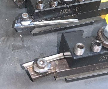
The China package was a tiny OXA tool post and holders to make tool changes less of a PITA and it works perfectly.
![IMG_3222[1].JPG IMG_3222[1].JPG](https://www.hobby-machinist.com/data/attachments/411/411940-21f331e7e926e75f42331653a528183c.jpg)
I removed the compound for rigidity, not sure this was necessary but making a custom plinth for the tool post to sit on elevated an issue of mis matched tool post bolt and compound thread I had. You can see the 3/16" tool bit under the tool holder here and yeah, I miscalculated when making it a bit as I was making the plinth while the tool post and holders were enroute. Going to need a do over on that one. Not terrible, it just lessened the adjustability of most of the holders to accommodate a tangential
(I like tan genitals) tool holder you can see in the next pic and was a mistake made via tunnel vision as I really like the versatility of that tool.
Its in the back of the lineup here and a bit out of focus.
![IMG_3223[1].JPG IMG_3223[1].JPG](https://www.hobby-machinist.com/data/attachments/411/411942-5267728c9223df643401c84e11f8f4cb.jpg)
Ill probably pick up a couple more tool holders as their only $13 each and then I can have everything mounted and ready to use when needed.
After getting that working it was time to focus my attention to mounting the ER32 collet chuck I got with this package. This included needing to make a backplate to fit it, and buying a backplate to copy. I found one for a 4 jaw chuck and bought that and copied same, and the fit on the spindle came out perfect which amazed me as I left .0015 on the inner diameter for fitting at home while making it at work.
Miraculously it fits so well that any slight tilt to it when installing locks it up tight, but it spins like its on rollers once in place and square.
Here I'm taking it down to the proper size and tediously fitting it to the collet chuck. Normally I wouldn't spend this much time on mounting a chuck (That's a lie), but being its a collet chuck I was going for broke.
![IMG_3206[1].JPG IMG_3206[1].JPG](https://www.hobby-machinist.com/data/attachments/411/411943-48691816663f3b9cd47b17528e1b9ffb.jpg)
Did I mention this was tedious? A small cut netted me peach fuzz. Don't forget, that is a tiny tool bit.
![IMG_3207[1].JPG IMG_3207[1].JPG](https://www.hobby-machinist.com/data/attachments/411/411944-7ed0c5d450527603cad4f71be8b3c0ea.jpg)
All done! Finish looks sketchy, but the flash picks up every microscopic detail.
![IMG_3208[1].JPG IMG_3208[1].JPG](https://www.hobby-machinist.com/data/attachments/411/411945-7e695dd3133c1f0be04d14a193bae83c.jpg)
And the fit I got for the chuck was easily as good as I got for the backplate to the spindle.
Here it is installed.
![IMG_3209[1].JPG IMG_3209[1].JPG](https://www.hobby-machinist.com/data/attachments/411/411946-48af34e0eabadfb12e1f74b7a0953905.jpg)
Now I got ahead of myself here. In order to make the backplate I needed a carriage stop so I could accurately form the shoulder the chuck mounts to. You can see half of in in the above pic. Only half because the completed stop was too long to get the tool bit as close to the headstock as needed to make the back plate.
Worked fine in any case, just wasn't micrometer settable like I wanted. It needs to be mounted to a rectangular bar that runs the length of the bed which protects the lead screw, so I had to be inventive and think outside the box on this one. I came up with a stop that with the turn of one thumbscrew
(4-40 thread for added clamping force) clamps down in 4 directions equally around the bar.
Here it is disassembled so you can see the details.
![IMG_3216[1].jpg IMG_3216[1].jpg](https://www.hobby-machinist.com/data/attachments/411/411950-23aae92f48e2c6023149dd7559f06229.jpg)
And assembled so you can see how it functions. The side plates are .020 thinner than the body and .010 shorter to the center of the dovetails. This allows it to float freely when unclamped, yet be rigidly and squarely fixed in place with only moderate screw pressure. A genius effort on my part if I do say so.

![IMG_3217[1].JPG IMG_3217[1].JPG](https://www.hobby-machinist.com/data/attachments/411/411949-bb120da194455aa5fe2211e7d5f05cfa.jpg)
And in place in its home. Its not finished yet, needs to be prettied up and some small details finalized, but I wanted to keep moving on the upgrades and will save that for when there's a lull in the work, like next time I'm out of cash for new additions and need something to do.

The micrometer body and dial was scavenged from an old tool cutter/grinder and is the icing on the cake.
Small at 1" on the thumb wheel, 3/4" on the on the micrometer dial and 5/8" on the barrel/body allowing the whole works to be around 1" in width and 1.5" length. Its tight under the chuck so everything has to be as small as possible and the 1" thumb screw knob and 4-40 screw allow ample clamping pressure with just finger tip
(And that's all there is room for) pressure.
![IMG_3220[1].JPG IMG_3220[1].JPG](https://www.hobby-machinist.com/data/attachments/411/411947-3fa573dd490149b3de23524ef938a241.jpg)
Once the fit of the chuck was finalized I added in some 3/8" holes around the perimeter for using tommy bars to help tighten the collets and indicated it. Once it checked out I marked position with punch marks on the chuck, back plate and spindle to assure accuracy when mounting it up.
![IMG_3214[2].jpg IMG_3214[2].jpg](https://www.hobby-machinist.com/data/attachments/411/411953-abb1ac47df345ec9ec38e529b8e887ea.jpg)
I chucked up a random piece of drill rod and set up the indicator and Initially got .0015 runout and was not a happy camper.....AT ALL! Then I retraced my steps and remembered this piece was a little gritchy going into the collet, removed it and found a burr on the end I had in the collet. Turned it and hit ti with a file and cleaned up the surface with some 400 grit paper and was much more satisfied with the result.
This now proved to be a huge success as I got less than .0005 runout, but my video wont upload for some reason. I'm going to have to work on that or retake it.
Kinda bummed about that.
ETA: FIXT it! Format issue.


![IMG_3010[1].JPG IMG_3010[1].JPG](https://www.hobby-machinist.com/data/attachments/411/411904-77d618e22d3123908db3193e42ac89f9.jpg)
![IMG_3011[1].JPG IMG_3011[1].JPG](https://www.hobby-machinist.com/data/attachments/411/411905-4eb6e4090313bf32514273b1595eea5f.jpg)
![IMG_3015[1].jpg IMG_3015[1].jpg](https://www.hobby-machinist.com/data/attachments/411/411906-eaac6ce8262b8171d5e5cea80092fb02.jpg)
![IMG_3017[1].jpg IMG_3017[1].jpg](https://www.hobby-machinist.com/data/attachments/411/411907-e387cadc88cb5fa7d95458c934eaa3c9.jpg)
![IMG_3222[1].JPG IMG_3222[1].JPG](https://www.hobby-machinist.com/data/attachments/411/411940-21f331e7e926e75f42331653a528183c.jpg)
![IMG_3223[1].JPG IMG_3223[1].JPG](https://www.hobby-machinist.com/data/attachments/411/411942-5267728c9223df643401c84e11f8f4cb.jpg)
![IMG_3206[1].JPG IMG_3206[1].JPG](https://www.hobby-machinist.com/data/attachments/411/411943-48691816663f3b9cd47b17528e1b9ffb.jpg)
![IMG_3207[1].JPG IMG_3207[1].JPG](https://www.hobby-machinist.com/data/attachments/411/411944-7ed0c5d450527603cad4f71be8b3c0ea.jpg)
![IMG_3208[1].JPG IMG_3208[1].JPG](https://www.hobby-machinist.com/data/attachments/411/411945-7e695dd3133c1f0be04d14a193bae83c.jpg)
![IMG_3209[1].JPG IMG_3209[1].JPG](https://www.hobby-machinist.com/data/attachments/411/411946-48af34e0eabadfb12e1f74b7a0953905.jpg)
![IMG_3216[1].jpg IMG_3216[1].jpg](https://www.hobby-machinist.com/data/attachments/411/411950-23aae92f48e2c6023149dd7559f06229.jpg)
![IMG_3217[1].JPG IMG_3217[1].JPG](https://www.hobby-machinist.com/data/attachments/411/411949-bb120da194455aa5fe2211e7d5f05cfa.jpg)

![IMG_3220[1].JPG IMG_3220[1].JPG](https://www.hobby-machinist.com/data/attachments/411/411947-3fa573dd490149b3de23524ef938a241.jpg)
![IMG_3214[2].jpg IMG_3214[2].jpg](https://www.hobby-machinist.com/data/attachments/411/411953-abb1ac47df345ec9ec38e529b8e887ea.jpg)
