RBW's adventures in tiny Industrial machines. Prazi lathe and milling machine score.

just found some impressive stuff... first Edelstaal tooling was made in Tenafly NJ..

Second, they made big stuff too.
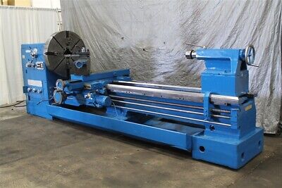
Yeah, I believe Edelstaal was originally an Austrian company who had a US branch in NJ.

They made the Unimat line beginning in the 50s or 60s and put out some really nice stuff aimed at the home shop types for that time. Seems like this tooling system was designed around the smaller machines and offered a cheap and easy way for the novice to get setup without having to first learn about cutting geometry's.

And as you found, they made or at least partnered with companies who made big machines also. That lathe seems to be a Yoder what was either made by or for Edelstall or vise versa.

I toured the Trenton Siemens plant during my apprenticeship a couple times when it was DEMAG DELAVAL TURBOMACHINERY and they had a similar lathe that was so big there was an operators stand that travelled with the carriage. Two men could stand on one side and a third on the tailstock side to operate the travelling tailstock. The machine was something like a 72" turning diameter by 40' long between centers and it had its own overhead crane that spanned the length to change out tooling and chucks.

The thing was said to have its own atmosphere when operated for long periods due to the heat from the chips and the airflow the heat created. The room was probably 60' high and you could see a mushroom cloud of smoke and coolant steam above it.

I have some pictures from there which are unfortunately lost in my house, and in one of them my buddy is sitting on a 5 ton lead hammer that is swung via a crane to gently bump 20 ton castings into place. The hammer had a brass face that weighed nearly 500lbs and was 2' across.

The small lathes in this place, their idea of a toolroom lathe was 18" X 90", truly massive machines.

Someday Ill find those pics.
 
Finally getting some parts together and time to work on this again.

I bought a servo motor kit from Dan at Custom Crafter for my lathe. If you haven't checked out his His Forum on this board you should. He has some really nice high tech drive solutions for many applications and the one I linked to is perfect for this lathe. It will give me variable speed as well as reverse at the touch of a button. No more changing belts only to be disappointed at the speed, High enough torque at low enough speed that the lack of a back gear becomes as non issue, and did I mention it has reverse?

With this I will be able to thread at whatever speed and direction (Towards or away from the chuck) I choose......Woo Hoo!

I'm not going to go into the bloody details of the kit (You can check those out at the link above), lets just say it is a very nice and well laid out solution to my problem at a reasonable price. The kit came very well packaged and included everything I needed save for the pully. Dan has pulleys available for many conversions, but I was looking for something special, and, well I can make the pully myself so that's what I did.

I also measured and brought some 3/8" and 1/2" thick aluminum plates to size for the new motor mount.

Here is the motor plate and the pully installed.


IMG_3436[1].JPG


Once I had that all prepared I needed to remove the factory motor and electronics. The electronics were mounted under the headstock portion of the lathe and as you can see, after removing them there will be ample room to mount the new control.

Cover plate.

IMG_3435[1].JPG


And here's the old controls and switches that will be removed next to the CC control box. Plenty of room.


IMG_3438[1].JPG


The Custom Crafter box this came with is very well thought out and has many nice details like wire strains and support ribs included in the design and this is made out of a high temp filament to resist heat. Good work Dan!

IMG_3440[1].JPG
IMG_3442[1].JPG


IMO 3D printed stuff always looks like hell in pics, but In my hands its very nice looking, if in need of a trim here and there.


First thing I did before removing any electronics was to short the capacitor. I've been bit by these before and they will store energy for quite a while. Unplugging the unit from the wall will not discharge a cap, you need to physically short the terminals.


IMG_3437[1].JPG


Once that was done it was a simple matter to remove the old wiring and switches to make room for the new goods.


Lotsa space.

IMG_3450[1].JPG


With that done I was able to remove the motor. The motor is mounted to a sheet metal plate attached to the back of the headstock. I will be making a new motor mounting plate that will also incorporate mounts for the belt drive cover and Ill be adding a muffin fan in here somewhere for cooling.


IMG_3427[1].JPG

The impressive thing about these servo motors is their size. I got the 750W (1HP) kit for my lathe and its overkill in all but slow RPM torque. That abundance of torque will be necessary in making the machine behave like it has a back gear when it does not have one. Having a much larger motor with more torque will help keep it from generating too much heat internally. When the motor runs at slower speeds, the fan cant provide sufficient cooling air too keep it cool, so you need more mass in the motor. This not a flaw with the design of the motor, its just the reality of a cooling fan designed to run anywhere between 300 and 4000rpm. A fan big enough to keep the motor cool under high load at low speed would fly apart at 4K RPM.


Here's the size difference.

The factory motor is 290W and is 3X bigger than the servo motor that is replacing it. Nearly 3X the power in a package 1/3 the size of the original.
with low to no vibration or noise. The factory motor was cool in that it sounded "Industrial" on startup, but that cool factor was greatly overshadowed by the extreme amount of vibration. That coupled with soviet era Bakelite pully construction caused the machine to vibrate quite a bit. Far too much to use an indicator with the motor running. I tried this one time and the needle was just a red smear on the dial.


IMG_3445[1].JPG


So now that the motor and electronics are out I have a clean slate for the install.

IMG_3450[1].JPG

IMG_3451[1].JPG
 
Last edited:
Been picking away at this as time allows and finally got the motor mounted, a pully made, and the control hooked up and it is fantastic!

I had to make a pocket in the motor plate to allow the motor to move forward so the pulleys would line up, and I had the opportunity to use the mini mill for this which was nice. The Mill worked great, and though it took a fairly long time milling out a 3"x3"x.260" pocket with a 5/16" endmill, the end result came out great.


IMG_3458[1].JPG

IMG_3469[1].JPG

I had made the mounting plate for the back of the lathe previously so all I had to do was drill three holes for the motor plate to mount to that and I was all set.


Everything bolted up nicely and while I need to replicate the factory pully out of aluminum to fit this motor, I was able to do a little testing. Of course I forgot to take any video (That will come later) but I was able to program the drive controller and check speeds and function.

I now have forward and reverse with a speed range of 30-1050 with the small test pully I made.

IMG_3472[1].JPG

IMG_3473[1].JPG


Once I replicate the factory pully I should get 20 to well over the factory 2200rpm, with gobs of torque all through the rpm range. In the limited testing I did I was easily able to take a .040 cut (Rad. not Dia) all the way down to 30rpm, and its nearly silent compared to the old motor.

A huge plus on a small machine like this is there are no motor vibrations....NONE.

This is huge as the factory motor vibrated the lathe bad enough there was no using an indicator while it was running, as the needle was just a blur.
 

Attachments

  • IMG_3471[1].JPG
    IMG_3471[1].JPG
    788.3 KB · Views: 4
Last edited:
Got another kit from The Custom Crafter today and got down to the actual final bits of the electronics install.

The actual drive board is fairly small, about 4"x4" with the back plate that acts as a heat sink being slightly larger. I could probably cut the heat sink down if needed, but Ill leave it as is as I have plenty of space to work with.


Here's the drive out of the printed enclosure it comes in.

IMG_3502[1].JPG


And the whole works inside the base of the lathe. You can see there is ample wire for whatever you may need, but for my needs Ill be shortening the wires about 18". This will give slightly better motor performance which is a plus, but Im doing this mainly for a cleaner install as loose wiring on rotating machinery is a no no.


IMG_3504[1].JPG


To shorten the wires I cut around the wire jacket and carefully slit it down the side.


IMG_3505[1].JPG


This exposed the wires so I could cut and solder them. A big bonus is if you're good like me:rolleyes: you nick the wires during this process so you know which wires to start with. Here you can see I nicked both the black and brown wires. To correct this I just cut the brown wire 1/2" shorter and cut the black one where the nick occurred naturally.

Yeah, that's it.:xmaslights:


IMG_3506[1].JPG


Here's a pic I took. No idea why I uploaded it, but take a look anyway.

EDIT: This pic was supposed to be two pics up, deal with it.:drink:


IMG_3511[1].JPG


So on to the soldering. I mentioned cutting the brown wire short, so from there I measured 18" down that wire and cut it off at that point and stripped both ends. I like to wrap both stripped ends around each other when possible for a bond that is both a soldered bond and a mechanical bond when I can.


IMG_3515[1].JPG


That pic is very out of focus (Dont adjust your dial.......) but you get the idea.


For the smaller wires I simply pre tinned each end and using a third hand devise and a pair of hemostats held them together for a straight solder joint. These wires were kind of small for twisting, but this should work well enough for this application.

Before


IMG_3521[1].JPG


And after soldering,

Good enough for government work.


IMG_3522[1].JPG


And I'm proud to say that I completed the whole project without forgetting the heat shrink tubing a single time.


IMG_3523[1].JPG


Added a couple layers of electrical tape to hold everything secure and slipped the little bootie on. Turned out nice if I do say so myself.


IMG_3525[1].JPG


Finally I remounted the motor and checked for proper fitment, turned out perfect.


IMG_3526[1].JPG


Plugged into the board with the board in place. Nice and neat.


IMG_3527[1].JPG
 
Last edited:
Got into a fight with Covid and was down for a week or so and didn’t get too much done. Last day I was out of work I felt good enough to get some more of this install done, so here’s that.


To start I decided to mount the control board onto the bottom plate on the lathe with some standoffs. The problem I encountered with this was the bottom cover was too flimsy and kinda soft being thin communist galvanized steel.

It was only .019 thick with probably .005 of that being the galvanized coating making it way too flexible for my liking.

So I remade this out of some .046 galvanized I had laying around.


IMG_3542.jpeg


With that done I cut down one of the bottom cover mounts to rid it of unnecessary portions and began to lay it out and see how everything fit regarding clearance and cable routing.


IMG_3543.jpeg


Then it was just a matter of making some standoffs and poking holes in the proper place, putting screws in and running the wires to it to double check fit.

Nice and tidy. A bit too tidy actually.

I had to fab up a new power cord and secure it inside the lathe and did that and plugged it into the board.


IMG_3549.jpeg


All buttoned up and ready to go, or so I thought.


IMG_3550.jpeg


Now remember I was just getting over Covid? Yeah when I plugged it in to check function I got no response from the power switch. Turned out I had boneheadedly bypassed the switch and wired power directly to the board.

Oh well, no harm/no foul, I’ll just have to make up a separate panel for the on/off switch/breaker that this system comes with at a later date.

It really wouldn’t fit in with how I plan to mount and position the main controls anyway, so not even another extra step, just something I missed.

No biggie.
 
Alright, got ahead of myself again and missed taking pics of some steps.


Here I’m making a satellite control box to house the control pad and speed knob off out of the way of the rest of the machine


What I did was cut and square up a piece of 3/4" aluminum and generally cleaned up all the sides. Then I put the squared block on a 30* angle and milled what will be the bottom at a an angle which will properly present the control pad face towards me for easy viewing when everything is completed.

Now to the pics.

I clamped the block in the vise with the angled surface down on the parallels in order to begin hollowing out the pocket for the controls. I had to be careful with this process as I knew from past experience when milling something out like this that will have thin walls (.070 and .050 respectively) that as you're removing material the vice will begin to squeeze in on the part and make these thin walls bow outward or inward and effectively reduce the clamping power the vise has on the part.


IMG_3563[1].JPG


With clamping forces lessening as I remove material I decided to hog material out in steps or teirs. Doing this allowed me to still take a good amount of material on each pass (Roughly .300 per step) while not imparting too much lateral force on the part that would make it want to rock itself out of the vise.

Here Im at my full depth of .800 on the X travel and about to begin milling out the steps.


IMG_3564.jpeg


Taking out the 1st step.


IMG_3565.jpeg


And once that one was gone I blued the bottom ledge so I could come near it without touching it. This was to be the .070 bottom wall of the part so I didn't want to take any extra, and as mentioned, things are starting to bow at this point with 90% of the holding material removed and I didn't want to throw the part out of the vise ruining it after doing this much work.


IMG_3567.jpeg


Turned out that being extra careful was a good thing as I heard a noise and stopped to find out the spindle nose began contacting the part. I readjusted the endmill at this point and came back to a touch above the final depth of the bottom shelf and was easily able to continue.


IMG_3568.jpeg


I came down to just a light touch on the bluing, not really even taking a cut, but rubbing the bluing off and finished up the rest of the angled portion of the pocket.


IMG_3569.jpeg


And here you can see the portion of the part that was bowed down where the bluing remains. I decided this was good enough as this will be covered by the control panel once everything is together. It’s only a couple thou but it does highlight what I was mentioning about the part deforming as you’re removing material.


IMG_3570.jpeg


And finally this step involving this setup is complete. Now I need to lay the part down and remove the rest of the material to form the rest of the box.


Once I laid it down I again had plenty of material initially to grip it firm enough that I could do some more hogging. IIRC I was taking .300 deep cuts for the first two passes and only .100 on the 3rd with .050 for the fourth and final pass.


IMG_3572.jpeg


Here you can see the rib I left in the center of the pocket. I did this for support as the floor of the part in this step as it is only .040 thick.


IMG_3574.jpeg


Then the last pass was removing that rib, worked out pretty well. Without the rib supporting the thin bottom it likely would have vibrated a bit and left a horrible finish.

This way the finish was only terrible.


IMG_3576.jpeg
 
Last edited:
hard to tell what y ou are doing. anxious for more
Next step will make it all clear.

I’m basically annexing two different components from one bulky box to two separate slimmer custom made boxes to better fit the machine, and get the controls where I would prefer them to be.

The way they are supplied from custom crafter is very well laid out and well made. They would go right on a larger machine with little if any modification needed.

I just chose this route because I have to do everything the hard way and put my touch on it.

I’m just bent in the head like that, but I love doing things like this.
 
Last edited:
Heh, I'm so good at this, for this post I'm going to start with the finished product and then go back to the beginning as I forgot to take a pic of the box by its self when I finished it.


Here is the completed control box and the corresponding arm to mount it to the machine. Their both obviously finished here, but your not paying anything for this entertainment, so at least you're getting your moneys worth.


I laid out the bolt pattern on paper and put those details in both parts, screwed them together with 5-40 flat head cap screws and milled a slot for the wires to pass through.

IMG_3585.jpeg


Once that was done I needed to deburr both sides of the slot so the wires wouldn't get chafed and one side was simple, I just used a countersink and chamfered it. For the other side I had to make a tool, a kind of reverse countersink. Here you can see it being readied to go into the slot.


IMG_3577.jpeg


I needed to turn it 90* to get it to enter, then turn on the mill and lower the knee to a depth where it would cut and go back and forth to clean up all sides.


IMG_3578.jpeg


This is the tool looking from the end of the tube. It hit the side wall a little bit in the back, but thats no big deal and Id rather that than to make the tool smaller and not have it big enough for something I might need it for in the future.

I literally have an entire drawer in my top box filled with one off tooling like this that I made for a single job, but that may also come in handy some day.


IMG_3579.jpeg


This is the finished product after deburring and hitting the edges with some sandpaper. Turned out good.


IMG_3584.jpeg


And I now present you with the completed box and arm assembled and ready to install.


OOooh, I'm getting excited to wrap this portion of the installation up. Its been roughly two months that I've had the new motor and control and I cant wait to use it. Its really going to make ruining the lathe a whole lot nicer having more power and control over the available speeds.


IMG_3586.jpeg


Bonus pic showing the shortened screws and the wiring slot in the background. I decided to trim the bar on a 45* angle as to make it invisable from the front when looking at the machine, otherwise I would have had to cap it to make it look finished.

The front edge looks off, but that was done on purpose and will look better when the panel is in place.


IMG_3588.jpeg
 
Back
Top