RBW's adventures in tiny Industrial machines. Prazi lathe and milling machine score.

Well I made some miscalculations.


The controller plug wouldn’t fit through my finely crafted and deburred cable slot.


IMG_3592.jpeg


Simple enough to fix, but much harder to deburr with the new keyhole shape. I simply took a 1/4" endmill and made a half moon cutout so the latch on the plug could fit through and that was that.

Next I had to bolt the arm to the motor plate and mill a "Correctly sized" opening in the two for the wires to pass through. I wasn't being picky about the size of the slot this time as I had plenty of room on this end and I also had to fish the wires out of the hollow extension arm, and too small of a slot would make that more difficult than needed.


So once I had them properly positioned and bolted together I cut the slot for the wires by making a series of overlapping cuts with an endmill.


IMG_3593.jpeg


Then I opened this up to match the inner dimensions of the tube.


IMG_3594.jpeg


And deburred it with a countersink.


IMG_3596.jpeg


And finally you can see everything together as it will be installed.


IMG_3597.jpeg


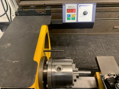
Once I got this all home I painted it with semi gloss black to match the rest of the black parts of the lathe. I got it all installed, stood back and was actually a bit disappointed by what I saw.


It looks like it came from the factory this way.


IMG_3608.jpeg


I mean, it fits and functions perfectly, but I was expecting it to stand out more or something, to look more custom.


Not blend right in like it was made this way.


IMG_3605.jpeg


Oh well, I guess I did a good job.

I still have to make another panel to go on the front where the three holes from the stock controls were. This will house the custom Crafter breaker switch and an E stop button for turning the machine on and off and of course acting as an E stop.

Now that it is installed in its final configuration I was able to do a little more testing. I did away with my shop made pully, and decided I would use the factory pully for now. Ill also remake an exact copy out of aluminum in the near future. The factory one is really bad com-bloc Bakelite which wasn't very concentric to begin with, that only got worse when I chucked it up on our Hardinge lathe and bored out the hole to fit the 15mm motor shaft.

It works for the time being and testing revealed these speeds.

Back gear speeds
L1 35 - 420rpm
L2 67 - 825rpm

High gear
H1 140 - 1550rpm
H2 270 - 2750rpm


With the availability of both high and low range and the wide speed range from the drive system, I'm more than happy with how this turned out. Im thinking Ill probably use it most in L2 as that seems to be the best combination of speed and power while letting the motor rev freely enough to keep it happy and cool.

I took a short video of it taking a .040r (.080 total) deep cut. This started at 35RPM and it goes up to 420RPM and it cut really well within that whole range.

This is 3/8" O-1 tool steel.


Thought I would also point out that there is 1-3/4" - 2" of sickout on that piece of 3/8" O-1 with little deflection, a testament to how nice that little chuck is.
 

Attachments

  • IMG_3606.jpeg
    IMG_3606.jpeg
    385.8 KB · Views: 3
Last edited:
Oh boy did I mess up.

Nothing major, but man did this take way too long.

My fellow Prazi enthusiast Wade (Pachyderm) saw the above video and commented on it that the lathe now looked naked with a big gaping hole where the fan end of the motor usta was, so I decided to remedy that next.

Now Im the kind of guy who keeps everything I think might come in handy one day and I knew (Thought) I had some louvered material, either steel of aluminum stashed away out in the garage next to the milling machine along with some road signs and other like stuff, So I went out to look and see what I had and realized I had moved this assortment of random items out of the way to work on the mill.

Alright, where did I put them? I had a couple of days of feeling despair thinking I had thought to throw them out as I've had them for a decade or more and never used them for anything. Found the signs and they weren't with them, and I finally found them in the most logical place, on the fender of my JD318 in a beer box.

I took some measurements and looked through what I had for louvered material and settled on this piece.


IMG_3619.jpeg


I cut it down to size and contoured it to fit the back side of the headstock and wanted to add some window screen to keep the chips from being blown inside. I found my window screen and looked for my spray glue which was no where to be found, then it hit me.

Use the paint I was going to use to act as the glue to hold it in place.

Brilliant! Or so I thought.

I cut a piece a little larger than needed and stuck it down with the paint/glue and waited for it to dry.


IMG_3616.jpeg


And waited........and waited......and waited.......for over a week.

This was the fiberglass kind of window screen as I knew the aluminum, which I would have preferred would never lay flat enough to work. Apparently the fiberglass soaked up so much of the paints solvent that it couldn't dry.

Finally I got tired of waiting and baked it in the oven at 275 two different times for a total of 10hrs to get the paint to the point I felt it was dry enough to not stick and become one with the back of the lathe.

Once it was dry I cut it to shape and was ready to install.


IMG_3644.jpeg


At this point I transferred the holes to be drilled and tapped, only to realize I had put them smack in line with the bolt holes that hold the motor mount plate onto the back of the headstock.


SON OF A BISCUIT!

Well I was able to find the 8-32 button head cap screws I needed in 3/16th length, so crisis averted as its only holding a Sheetmetal plate on.

Here's what it looked like with the poorly placed holes and no cover.

Kind of unfinished looking.

IMG_3643.jpeg


But with the plate on it now looks like it came from the factory that way.

I like it!

IMG_3646.jpeg


And incase you're wondering why my toolholder plate on top of the hesad stock is that funny shape, its because it is a part from a mobility scooter I scrapped that I saved incase I needed some 1/8" sheet metal. I covered this with 1/16" rubber I had so the vibrations wont send my tooling and whatnot onto the floor.

Which reminds me, that was the last time I saw my spray glue.....
 
Last edited:
Been working on the lathe but not posting in this thread as I thought I had a valuable "Teaching moment" to share with a wider audience.

After getting the motor installation finalized (Somewhat, more on that in a bit) I decided the factory motor and final drive pullies left lots to be desired. They were made out of bakelite and easily the absolute worst part of this machine and caused way too much vibration.

So Im making new precision pullies to eliminate vibration.

Got the motor pully done and it came out great. But now I need to do the spindle pully, so keep an eye on the above link for that.

Here's a short vid of the spindle pully to give you an idea how bad these were. These pullies aqre made in a 2 piece mold and if the molds do not line up correctly the pully winds up more of an egg shape than round.

I like round, round is good for high speed rotating parts.

If you think the indicator tells the tail, check out the humpty bump going on with the belt on the pully next to the one being indicated towards the end of the video.


So here's where I'm at. I finished the motor pully and needed to mount it to the motor shaft. I intentionally created a very close tolerance fit of the pully to the motor shaft to reduce or eliminate runout, both axially and radially.

Part of doing this was fitting a key between the two parts. Now you have heard people talk of "Fitting" a key, but why do they say this?

Well its because sometimes you want something better than "Hotdog down hallway" fit for something, as is the case here. If you're putting a clutch on a minibike engine, key fitting is a waste of time, on this lathe though it is worth doing.

I started out bluing the key with a fat blue sharpie. If you don't have a fat tip blue sharpie, get one. Dychem works well for certain situations, but its sometimes too thick for certain jobs and a layer of marker is 5X thinner than even the most well applied thinned Dychem.


IMG_3706[1].JPG


With that done I put the key in place and tried to slide the pully over it. It only went on so far, so I pulled it off and looked for a witness mark telling me where I had to take material off of the
key.

It completely wiped the bluing off of the side of they key, but it did slide past so that's OK.

IMG_3709[1].JPG


But the top of they key was hitting so hard it was shaving the inside of the keyway. If you look close you can even see the shaving on the key, then next pic on the motor shaft.

This I set up on the mill and took a .005 cut off of the top.


IMG_3710[1].JPG


Once that was done and the pully would just slide onto the full length of the shaft and past the key I was able to measure how much to trim off of the motor side of the pully to get all the sheaves in line.


IMG_3703[1].JPG


Looks like Ill need to take .120-.150 off for a perfect fit.
 
Last edited:
Been a while, but if you look at the pullies thread you'll see I've been busy making and correcting mistakes. Anyhow, the second time was a charm for the spindle pully and I got that installed.


IMG_3777.JPG


Now that I have the spindle pully finished and looked at the set screw holes between the two Im not sure how much I like that 1/4-20 screw hole with how much it projects into the V groove.

I may make that one again, I might leave it. Time will tell.


IMG_3778.JPG


And in those two pics you may have noticed some electrical components, which can only mean Im zeroing in on completing the electronics portion of this job. I picked up the tiniest lil E stop button off of Ebay after much searching, and while a bit pricy, its really nice.


Here I have already began making the panel for mounting these in and you can see it and the switches in their (Or near) their respective mounting places. The panel has a little gutter on the back corner to catch and errant liquids from getting into the switches or electrical components. The E-stop is water proof, but the power switch/breaker is not so Ill have to recess that a bit and give it a drip edge to protect it.


IMG_3779.JPG
 
Well, I think I'm finally coming to the middle here.


Got the control panel roughed out and ready for mounting. I had to cover the three factory switch holes so its a little longer than needed, but I think it looks alright. There's room for a fan on the right side if I decide to add one (blued area), but I'm torn on that. A fan would be mostly to aid in keeping things ventilated and dry vs for cooling, but I'm not sure either is necessary.

You can see a little beveled "Gutter" on the edge where it meets the lathe base. I added this to the top and sides to catch and divert any errant liquids away from the switches. It doesn't show up too well, but I have it bolted on in this pic so you'll have to use you're imagination. I just knocked back the corner off with a 7/16" ball mill to form the troth.


IMG_3967.jpeg


Now that I'm down to finalizing the electronics and had to take everything apart for that, I figured it would be a good time to get the change gear cover fitted back onto the machine. I had been dreading this part as my new aluminum back plate that holds the motor mount is much thicker than the original steel plate. When making this I wanted it to be "sufficient", but needing to free up some space I thought about it and realized that this part is in tension due to the belt tension and doesn't need to be too thick.


Put it up on the mill and took the flanges down to the same .090 that the steel plate was.


IMG_3960.jpeg


Anyone remember that broken tap? I decided to get that out so everything looks properly finished when all together. Missing bolts are not a sign of quality work and since I may be selling this when finished due to getting the SD400 lathe, I felt it prudent to clean this up.


Here I carefully spotted it flat with a 3/16" endmill.


IMG_3957.jpeg


Carefully ran that through (2500rpm) and I was left with just a shell of the tap remaining.


IMG_3962.jpeg


Knocked that and some other bits out with a hammer and scribe and had a good, if not too neat hole. The punch marks in the previous pic got milled off as I had to shorten the mount to compensate for thinning out the mounting flanges on the back plate.


Tap bits.


IMG_3965.jpeg


Now we get to the nitty gritty details I was dreading.


Here you can see where I marked a support rib that is spot-welded inside the gear cover in order to shorten it. This was needed to fit it in that very blurry groove I milled for clearance (Top of pic) in the adjacent part of the back plate. I decided to split the difference between milling a slot for this to full depth and leaving extra meat on the plate to support the motor better.


IMG_3972.jpeg


Once this was done I found another area of interference where the cover was hitting the back of this plate when trying to install it. This cover is hinged, but does not close like a door. Rather you swing it into place on the hinge (really just a long rod seen in pic above) and slide it down over everything.

This would slide down only so far, then bind up. You can see where it was rubbing/binding on the paint near the now shortened support rib and hinge mounting screw near the top of this pic.


IMG_3974.jpeg


In order to clear that, I set it up on the mill and flycut .050 off of this face. You can see the groove cut for the support rib better in this pic.


IMG_3973.jpeg


So, yeah, remember that screw? It wanted to have a say in things so I had to mill clearance for that too. Everything was becoming a PITA at this point, but its the little details that make things work right.

I see you in there....


IMG_3977.jpeg


And finally after another half hour of fitting, fettling, finagling and filing, I had a perfect fit. It never went on/off well from new, but that is just the nature of a Sheetmetal housing going on to a square machine and fitting tightly.

This needs to be a tight fit so it wont rattle during operation, and Im happy to say it goes on and comes off better than new.


IMG_3978.jpeg


All of these pieces need repainting as many scratches were made moving them around to work on the different angles, but this will come when the control panel gets finalized and painted.
 
Finally made some headway on the control panel, but it fought me every step of the way.

I needed to paint it before putting the switch and E stop on and the paint fought me every step of the way. Had it finished Super Bowl Sunday and baked it in the oven at 250f for three hours and went over to my brothers to watch the game.

Got a text right as the game was starting that my wife set the oven at 400 to preheat and smelled something burning. Yeah I had forgot to mention to her I had a part in there and the paint damn near baked right off.

Sandblasted it to bare metal, Reprimed and repainted and finally got a good result.

IMG_4027.jpeg

Then I was able to start finalizing the wiring to connect the E stop and the power switch.

Now for a little product placement. I have been buying items from a company called Couty comm for a few years now and knew they had a really nice set of helping hands that would improve my wiring/soldering/small parts assembly game, so I finally sprung for a set and boy I'm very glad I did.


Here I'm using them to lengthen the yellow control wire in the control circuit in order to link it to the E stop switch. Doing this will give me a work around of the way the drive control works from the factory. From the factory you need to turn the speed pot all the way off to get the machine to stop and then reset your speed for every single time you want to turn or off the spindle.

This is time consuming and confusing and really breaks up your workflow.

Linking this to the E stop button yields a simple On/Off function along with an actual E stop function to the controls.

Pretty slick.

Here are the County Comm helping hands holding the tiny yellow wire perfectly in place for soldering.


IMG_E4032[1].JPG


IMG_E4033[1].JPG
IMG_4034.jpeg


Here is a link to these items. I have no affiliation to CC. Just passing this on as these really are a great addition to your shop. They are so much better than the cheap alligator clip type hands and these have the benefit of being able to be mounted permanently to the bench or mounted to solid movable stands for better placement and articulation. I'm going to mount mine to some heavy movable steel bases once I work out a viable storage solution for the whole kit.


And with that all wired up we have a nice clean install that also functions very well. I think I did pretty good in keeping everything I have done with the controls looking like it could have come from the factory like this.


IMG_E4038[1].JPG


I hate how much glare my fluorescent lights give to the subject matter, so just factor in it looks much nicer in person.


IMG_4037.jpeg


Im going to have to redo some of these pictures and also this video, so bear with me.

Video of the lathe in operation with this new control setup.


Last edited:
Here are the County Comm helping hands holding the tiny yellow wire perfectly in place for soldering.

View attachment 479975
View attachment 479976
View attachment 479977


Here is a link to these items. I have no affiliation to CC. Just passing this on as these really are a great addition to your shop. They are so much better than the cheap alligator clip type hands and these have the benefit of being able to be mounted permanently to the bench or mounted to solid movable stands for better placement and articulation. I'm going to mount mine to some heavy movable steel bases once I work out a viable storage solution for the whole kit.


Those are so cool!! I placed something similar in my wishlist in Amazon. I saw them on one of the videos from Adam Savage

Single:


Single.jpg

Double:


Double.jpg

But the ones you shared the link are less expensive and look to work just as well... Thank you for the link. I will be ordering a few of those. Cool!!!
 
Those are so cool!! I placed something similar in my wishlist in Amazon. I saw them on one of the videos from Adam Savage

Single:


View attachment 479986

Double:


View attachment 479987

But the ones you shared the link are less expensive and look to work just as well... Thank you for the link. I will be ordering a few of those. Cool!!!
I made a thread about these in the tool section.

In terms of quality I think the CC offering is a bargain in comparison. Better quality with machined vs stamped parts.

Original price was something like $56 each! I wanted them bad, but not that bad.

$60 for the pair I could afford and may even copy the clamp part for a 3rd or even 4th hand as you get plenty of spare components with each kit.

Even a replacement spring.
 
Back
Top