Redlineman's Logan 200 Rescue

Hey;

Correct. Using an Arkansas red stone to take down nicks and dings and smooth out the surface. Sort of like clay bar on your car's paint, the stone floats on a layer of oil laid down first, much like the carriage and tailstock in normal use. The stone hits any raised areas from impacts and takes them down flush. Obviously you don't want to go so far as to remove the original flaking, since you can't take enough off to remove the dings anyways, but taking the high spots off the dings makes a HUGE difference in how components slide on the ways. You can feel the drag lessen as you continue to stone, and in fact, the function of the stone fairly ceases once the high spots are gone. This is your cue that you are done. It also brightens up the surface and gives a nice contrast to the flaking.

Just paying the inspiration forward! :drink:
 
Redlineman: Thanks a bunch for the technique/tips.

Just a few months ago, I tried the auto body clay you mentioned. That stuff is amazing for cleaning junk from clear coat paint.

Can you tell me if there's any particular stone hardness or size that works well? I was checking the web for stone sizes, and many are 2 x 8 inch, which appears a little cumbersome for the small dimensions of the bed ways. There also appear to be a few Arkansas stones available in the 1 x 3 size, but not too much info on the grit (just soft, medium or hard).

Happy New Year!
 
Frankly;

I have no idea what it is. It is Norton brand, red, and about 1x3. Perfect size for the sides of the Vs, as well as the flats. Judging by the fact that it is very old and yet has no surface wear, I'd guess it is at least a medium if not a hard. Your clay experience will stand you well. The process is much the same, and some of the feel should be as well. You'll remember that feeling when all the debris is loosed from the paint surface. The clay bar just floats. Same thing here.

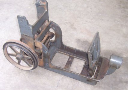
Last night I stripped the motor stand assembly base and the motor bracket LA-383. I don't know the part number for the early motor stand base because I have never seen a diagram that shows it. The only diagram I have ever seen is for the later bench version LA-17. If you look at the drive box assembly diagram LA-16 in my post #37 in this thread, you can just see the point where it bolts to the the bottom of the drive box LA-374. I'd like to see/have one of those early diagrams, if they ever existed.

Anyway, the paint is dry on the tailstock body, so I could assemble that. I think the only thing not stripped and ready for paint is the belt guard door and the pipe leg for the motor stand. Time to paint some more bits!
 
Frankly;
I have no idea what it is. It is Norton brand, red, and about 1x3. Perfect size for the sides of the Vs, as well as the flats. Judging by the fact that it is very old and yet has no surface wear, I'd guess it is at least a medium if not a hard.
Since Redlineman's stone is Norton and Red, that should make it a Norton India oilstone (probably fine). They make them in a coarse, medium and fine and are available in many configurations. These stones are aluminum oxide, and a bit harder than the Crystolon stones (grey silicone carbide). The fine stones are an orange, red, brick color and I'd say around 320grit. I think the med India stone is more of a sandy color. And I am not sure on the coarse (they don't make one for my application below).

I have an old Norton Tri-Stone set up (think butcher's knife sharpening). Typically for these you'll find Crystolon coarse and med stones. These would be for "grinding" a new edge on the blade fast, and the stones do wear. The fine in this type of set up is generally a fine India and puts a very nice edge down and wear very little. You may never notice the wear (on any of these stones) in a home situation ... but in a butcher shop/meat packing situation ... the India stones are definitely harder.

With any of the above stones, it is important to keep them flooded with oil (mineral oil is great). It is the oil that carries the "junk" out of the cutting edges of the stone and prevents it from clogging.

Hope I did not get carried away, LOL. And I'm not saying that any of these are the correct stone to use (although the fine India sounds logical to me). But it is some info on these two types of Norton stones.
 
Redlineman: I believe there's an isometric view of the LA-17 Bench Stand Assembly in the Logan manual for the model 200. It follows the page which details the LA-960 bed assembly. The cast bracket between the Drive-Box and the Motor Bracket appears to be LA-391, but I have no idea why that part is called a "Bench Stand". The part numbers didn't come thru clear on the drawing, so I'm going off the bill of material and weight info.

Mister Ed / Redlineman: Good info on the stone selection. Those smaller stones were a little tough to find. I just ordered a slightly larger set from an online sharpening supply store. Hopefully I'll have the stones sometime next week.

Now I'm wondering if JB weld is soft enough to fill some of the scrapes in the top of the v-ways, and flatten out with these stones (I'm assuming this is cosmetic only, since the flat sides are OK). My bed isn't quite "clunker" status, but I certainly won't see any original finish marks. Hopefully, this suggestion hasn't caused any cardiac arrest the true craftsman types.

Good luck finishing the paint work.
 
Good stuff on the stones, Ed!

Hey Tom;

I think they call it a bench stand because that is exactly what it was intended for. Add the legs and pan and you've got a floor model. The real problem is that the LA-17 schematic depicts the late model system. The early type is very much different. If you look at LA-391, then LA-1084 is the peg and 0647 is the rubber cap. LA-396 pedestal leg sits under the peg/cap. The early 200s had a large base casting with two set screws and a pipe leg. Much different. I've not found a schematic for the early type yet.

Logan200EarlyMotorFrameLA-17.jpg
 
Redlineman:

For some reason I mistakenly thought the pipe and setscrew setup was the newer version (compared to the cast pedestal). I just noticed that the drawing in the manual indicates the pipe pedestal drive box was used until SN 40115.

There's no isometric view, but page K-2 of the manual reprint has a decent side view of the pipe/setscrew setup. That setup sure makes it easier to swap out the pipe, to work with your 4 inch riser blocks (assuming it's a standard size pipe).

I hope your painting is coming along faster than mine. I was solvent washing the Bench Stand casting and noticed a few deep pits, so now the filler is curing. I have to find something softer than JB weld. It sure takes quite a bit of sanding to blend in.
 
Tom;

Just use regular polyester body filler. Bondo. Sets fast and sands easily.

As for the early peg leg, I'd be surprised if they built another 25k lathes after mine with that setup, taking serial numbers numerically. I'm inclined to think that Logan changed their numbering scheme in there somewhere.

You know... I never even thought about getting a longer leg.... :nuts:
 
Last edited:
-

More small morsels;

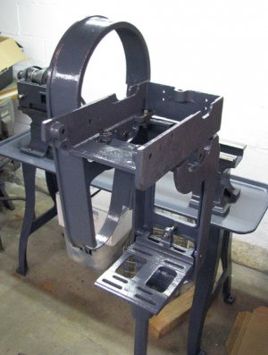
LoganFloorStand1.jpg

When you are taking stuff like this apart, you don't really think about any difficulty in reassembly. I mean, it's pretty basic stuff here, eh? Well, even on so basic an assembly, there are many little details that do not register and will easily slip away from you. For those gathering courage by reading this thread, I will offer a huge piece of sage advice; TAKE PICTURES! Take a stupid amount of pictures from a lot of angles, trying to capture every detail, every part, every fastener. Yes, I took a fair number of pictures, but in the end seemingly not enough. I have managed to catch some small details that were crucial in figuring out how something was supposed to go, but sometimes it was purely by accident. Here's an example;

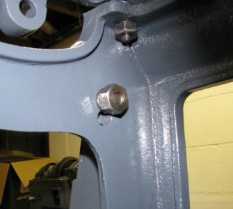
LoganGuardFrame2Holes.jpg

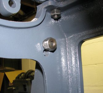
This is the rear bolt that holds the Guard Frame LA-394 to the Floor stand LA-377. Mine has two holes, the use of either altering where the Pulley LA-912 will sit inside the guard frame. Not only do I have no clue whether this was original to these lathes or added by someone to overcome some marginal non original hardware arrangement, but I could not remember which hole had been used previous to my tearing it apart? I got lucky, and a photo I had taken to show how the motor was mounted just happened to catch a glimpse of this spot in the background. You can NEVER have too much information when it's time to reassemble. TAKE MORE PICS!

I also had a happy discovery. All the parts were grouped and bagged upon disassembly as you would expect. One of those bags had wandered off, visiting various locales over the last year - my basement shop, my car, my business shop, etc. I remember them in those places. At some point that bag kind of just slipped under the radar. It was the bag with all the compound rest hardware in it. That little sandwich bag containing over $200 of prize bits had gone missing. All the obvious places checked failed to produce said bag, and ideas were getting slim. Damn... Quite why they had made it to my dresser I'm not sure, but it was good to know that I'd put them somewhere safe... if only moderately illogical! I'll need to have a look again to see if there is anything in need of repair or replacement. Sure would be nice to have the dough for new feed screws and nuts!

One thing I know I need is a motor pulley LA-349/1037. My motor is a non original 1/2 horse GE with some generic single pulley installed. If any of you boys have a spare original pulley for a 5/8 shaft you'd entertain selling, I'm interested!

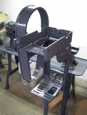
LoganFloorStand1.jpg

LoganGuardFrame2Holes.jpg
 
I have a complete drive unit from a 200 if I haven't robbed the pulleys for a past project. If I get time tomorrow I'll see what I have.

Chuck
 
Back
Top