Vectrac CNC Knee mill refit from Fanuc 0M to Camsoft

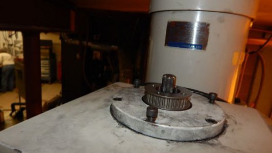
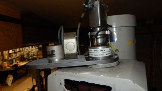
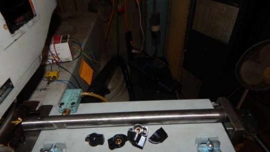
Spent the last several days mounting an encoder to the spindle. had to get real clever here. Only got about 1/4" of the top of the hollow spindle exposed and it can't get in the way of the tool changer. The pics show the parts and the final completed project.

A spindle encoder really increases capability. It allows the spindle to be treated as a galil axis to control the spindle VFD. S codes for programming spindle speed are now a piece of cake. Rigid tapping can now be done. if a 4rth axis is added, it can be slaved to the spindle to hob gears. By comparing analog command voltage (Galil TT) to spindle speed, it is possible to determine where the adjustable speed pulleys are set.spindle encoder tool changer  parts.jpgSpindle encoder pulley.jpgspindle encoder complete.jpg
 
That is very creative, I may copy that one.
 
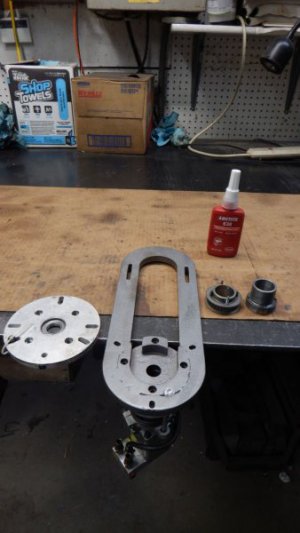
I see I neglected to explain the concept here. The bushing at far right in the parts pic just slides inside the hollow spindle. I drilled tapped for two #6-32 screws on the end of the spindle. two of the four screws in the bushing fit here. The other two are tapped and function as jack screws for disassembly.

The red bottle in the pic is bearing retaining compound. the lower part of the bushing is coated with this and slid into the top of the spindle. two screws hold it in place. If it ever must be removed it will need to be heated to break the bond. I put a note to this effect on the tool changer. doubt I ever tear it down. The note is for some poor soul in the future.

The pulley in the pic fits on the top of this bushing. The two tapped holes also function to hold the pulley on. I did not use retaining compound here.
 
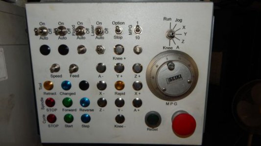
current work has been the machine operator panel. IMHO, the biggest difference between a profession quality and a hobby quality refit is a great control panel. A lot of thought went into this one to make it exactly as I want. I like to be able to run the machine from the control panel but not have it look like a 747 cockpit airplane control. Some things are better done on the PC keyboard and function hot keys.

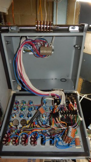
This one needs fifty conductors for all the I/O, see the pic of the inside got pretty crowded in there. I also placed it high and ahead of the spindle to keep flying swarf away. It lined up so that I needed to extend the backgear lever. this made it easy to add an input for backgear with a limit switch, see pic.

control panel.jpgcontrol panel inside.jpgback gear input switch.jpg
 
I feel like I am standing at the base of a very tall and steep mountain, looking up at your project....
 
Thanks for the compliment. This is my fifth Camsoft install. I did a couple AHHA (DOS stepper control) and a Mach 2 before that. Things do get better with practice.
 
ARGH - a step backward.

I lost the eight inputs on the second Galil card. Had two working, one was the estop input. Now all eight are dead. I double checked by booting up Galil WSDK. the first eight on 1900 ICM one are fine, second eight on 1900 ICM are all dead. FWIW, have +24 for signal, DC common connected to INCOM.

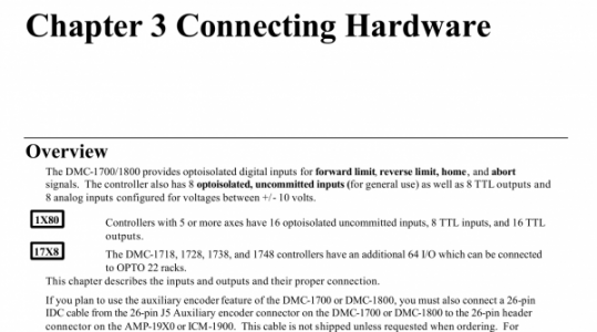
I double checked manual, see attached pic, they are all opto isolated so 24 volt should be no problem.

<Jim> See anything wrong? What component is most likely zorched?

karl
Capture.PNG
 
First I would swap the cables on ICM 1900-1 and ICM 1900-2 to see if it's the card or the ICM. I have also had this problem when the 100 pin cables are not well seated.
 
Back
Top