-
Welcome back Guest! Did you know you can mentor other members here at H-M? If not, please check out our Relaunch of Hobby Machinist Mentoring Program!
You are using an out of date browser. It may not display this or other websites correctly.
You should upgrade or use an alternative browser.
You should upgrade or use an alternative browser.
Vectrac CNC Knee mill refit from Fanuc 0M to Camsoft
- Thread starter Karl_T
- Start date
- Joined
- Oct 14, 2014
- Messages
- 2,106
I wired mine ACM to ANG and AO to AN1. Scaled it in my software, reads 0 to 150%.
Thanks for the wiring instruction.
I'm curious on your math to the load display. Do you allow for less available power at low RPM? This 2J style head has adjustable sheaves for more torque. I'd like to see a warning when the set speed has the RPM too low and the machine is approaching too much load because of the low motor RPM.
Another way of saying this. I've got a number that is basically amps from this meter. I've also got RPM from Galil tell torque. What would the math look like to give a load meter based on available torque??
- Joined
- Feb 8, 2014
- Messages
- 11,176
The load meter just reads the output amps scaled as a percentage of the motor rated amps, normally in the range of 0 to 150% In SLV mode the VFD will try to keep the motor at the set RPM by increasing the current to the motor up to the upper set limit, at which time the VFD trips out. In SLV mode, the VFD will try to produce maximum torque, if needed, at any RPM below the base RPM (normally 1800) (constant torque) and above the base RPM will try to produce maximum HP (constant HP) by varying the torque (current) as needed to maintain the set RPM without overloading the motor.
To put this another way, let's take the case of a lawnmower engine. These are governed to about 3600 RPM at max throttle. So when running unloaded, the governor is opening the carb butterfly only enough to produce enough torque to maintain the engine speed. But when you start cutting grass, the governor is adjusting the butterfly to try to maintain the set RPM based on the load, producing only enough torque to maintain the RPM. When you hit that heavy patch of grass, the butterfly opens all the way to try to maintain RPM, this is the max torque that the engine can produce. If the torque required is greater than the engine can produce then it stalls.
You're wanting to torture the load meter into being a HP meter. RPM doesn't enter into the math. The _TT command doesn't give you RPM, but rather the ''throttle position'', and the load output from the VFD gives you the ''torque'' (current draw) value as a percentage of the maximum available torque. You can calculate the HP, but this would require an encoder or tach input to the Galil.
Or another way using the formula (V * I * Eff)/746=HP, determine your electric motor's horsepower. Multiply the voltage, the current, and the efficiency, then divide the result by 746. For example, the horsepower of a 230v motor pulling 4 amps and having 82% efficiency would equal 1 horsepower. This would be difficult to implement because there is no easy way to read the instantaneous output voltage to the motor.
Bottom line is the load meter should just read the load output from the VFD, scaled as 150%=10V or ANin * the scale factor (1/(150/10)) = 0.066
I hope this makes sense.
To put this another way, let's take the case of a lawnmower engine. These are governed to about 3600 RPM at max throttle. So when running unloaded, the governor is opening the carb butterfly only enough to produce enough torque to maintain the engine speed. But when you start cutting grass, the governor is adjusting the butterfly to try to maintain the set RPM based on the load, producing only enough torque to maintain the RPM. When you hit that heavy patch of grass, the butterfly opens all the way to try to maintain RPM, this is the max torque that the engine can produce. If the torque required is greater than the engine can produce then it stalls.
You're wanting to torture the load meter into being a HP meter.
Or another way using the formula (V * I * Eff)/746=HP, determine your electric motor's horsepower. Multiply the voltage, the current, and the efficiency, then divide the result by 746. For example, the horsepower of a 230v motor pulling 4 amps and having 82% efficiency would equal 1 horsepower. This would be difficult to implement because there is no easy way to read the instantaneous output voltage to the motor.
Bottom line is the load meter should just read the load output from the VFD, scaled as 150%=10V or ANin * the scale factor (1/(150/10)) = 0.066
I hope this makes sense.
- Joined
- Feb 8, 2014
- Messages
- 11,176
Maybe this one https://www.rls.si/eng/re22-rotary-magnetic-shaft-encoder
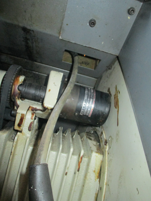
Looks like the belt is a bit out of alignment. You could be putting too much radial load on the shaft. The bearings should hold up to high speeds with no problem.
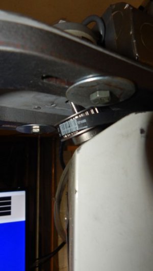
Here is a picture of my lathe spindle encoder, you can see that the drive shaft and pulley is mounted in bearings, and the encoder is connected by a flexible coupling to the shaft. No radial or axial load on the encoder. You may have to do something like this.

Looks like the belt is a bit out of alignment.
Here is a picture of my lathe spindle encoder, you can see that the drive shaft and pulley is mounted in bearings, and the encoder is connected by a flexible coupling to the shaft. No radial or axial load on the encoder. You may have to do something like this.

- Joined
- Oct 14, 2014
- Messages
- 2,106
OK, got the spindle all up and running with S codes to command speed. I ended installing a new encoder from Automation direct. Had a bit of trouble with the test spindle routine but got it going with Camsoft support.
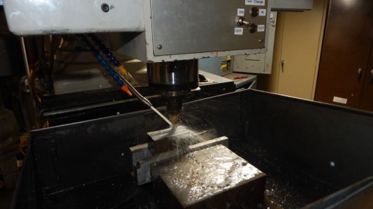
Yesterday did the bloody awful job I've been putting off, final cleanup of the coolant sump. Some real nasty sh*t has been growing in there for years. turned out to be easy once set up. I cleaned out my wet dry shop vac and set it up to suck water. Set up the hot pressure washer. Alternated between washing and vacuuming till it was clean. Did **** off SWMBO as my clothes looked like I had been swimming in a coolant sump. I looked about the same.
Today, got the home routine debugged and soft limits set up. Just a tiny bit of work left for tool change logic.
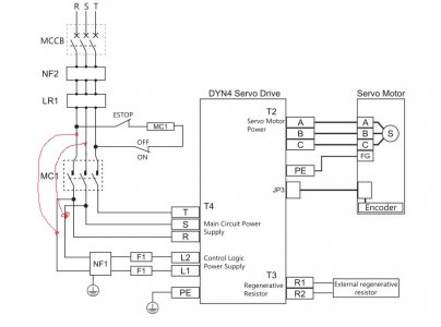
Did a trial of Estop when running G0. Machine losses position. Not a huge deal as this should only happen in a true emergency and the machine can be re homed. Also if axis are moved by hand under estop, machine does not see the move. I wonder if a re-wire as per the red lines to by pass E-stop would cause problems? I've left encoders powered under Estop on my other installs.

Last edited:
- Joined
- Feb 8, 2014
- Messages
- 11,176
Did a trial of Estop when running G0. Machine losses position. Not a huge deal as this should only happen in a true emergency and the machine can be re homed. Also if axis are moved by hand under estop, machine does not see the move. I wonder if a re-wire as per the red lines to by pass E-stop would cause problems? I've left encoders powered under Estop on my other installs.
I had a bit of a problem wiring a Dyn4 drive the way you propose. On energize there was a possibility of a short period runaway, maybe a few motor turns, before the encoder and Galil synced up. Never did actually figure out what was happening. This was on that servo press I built. A bit unnerving but no harm done, both drives were free to turn. On a mill it would be a different story. I rewired it so the control and power energized at the same time and ended the problem.
On the lathe, the only thing I saw was that the live tool servo was confused on energize, but it's free to turn so again no harm done. But I rewired the drives to energize the controls on powerup. Didn't want to take any chances. I just home it after an E-stop. On my mill, I do leave the encoders powered and it would really suck if I didn't have that. The only time I lose position is on a complete power down, but my mill is not powered by DMM servos and has linear encoders.
Bottom line is I recommend you leave it wired as it is. Alternatively you could add linear encoders to the mill and not use the DMM encoders at all. Your controller doesn't care where the position data comes from.


