Mike's SCARA Robot

Called Yaskawa to talk about their motors and was very pleased with their technical support. The "SU" in the motor catalog number indicates a Seiko proprietary catalog number which prevents Yaskawa from providing me any information on the motor even though the robot and series of motors are no longer manufactured or supported. This is pretty common in industry to prevent an end user from trying to find a cheaper replacement part by going direct to the manufacturer.

I am fairly confident that electrically the motors are identical to their normal counterparts without the "SU" in their catalog string. I hope that any differences are limited to shaft size, paint color, or something else that doesn't affect what I am trying to accomplish. This may also have allowed Seiko to specify the type of connector on the end of the cable to make integration easier for them into the robot.

According to their support engineer the encoders do not have any commutation signals and were painstakingly aligned to the motor electrical angle at the factory using an oscilloscope. Unfortunately this doesn't answer all my questions because the motor would need to rotate until it found the "z" index pulse to know where it was. The engineer told me he didn't know how exactly it worked, but it certainly did not need to move at startup. It is looking more and more like I will need to use commutation self sensing (if my drive supports it) or replace the encoder.
 
Wow, what a project!!!!

I can see why you wanted one of these things and I'm sure you have some idea of what you'll do with it once it's up and running. Any chance it will integrate with another machine or process to make things easier in the shop?


John
 
Wow, what a project!!!!

I can see why you wanted one of these things and I'm sure you have some idea of what you'll do with it once it's up and running. Any chance it will integrate with another machine or process to make things easier in the shop?


John

Thanks! Honestly as with many things I do in my shop it is more about the enjoyment of the build than it is needing the end product. Right now it is sitting on a table with a whiteboard top so the first thing I will probably have it do is draw some stuff. Probably a good way to make sure the motors, drives, and programming is working correctly.

Down the road it would make an absolutely overkill toolchanger for my CNC if I wanted. I looked into it real quick already and I can make my PLC talk with Mach 4 over Modbus TCP really easily, so it would be as simple as Mach 4 sending a start command to the robot and a requested tool, then the robot going and picking up the tool from a rack and swapping it for the one in the spindle. Probably would be pretty easy to get it working like one of those side mount pre-load tool changers on most modern CNCs. Neat application but not really why I am playing with it.

I actually tried building an ATC 2-4 years ago and it worked but was never going to be reliable. It ran on an arduino and Mach 3. The programming was shoddy, the Modbus crapped out a lot, and the thing was tremendously complex. I would have had to spend a lot more time and money to get it running well so it sits on the shelf of shame for now.
 
I have updated the first post with all the new information that I have. Most of this is motor data from Yaskawa. I was able to confirm that the motors are electrically identical to the normal SGM motors to the best of my knowledge, so I will be going forward with that assumption.

I require motor winding resistance and inductance for my servo drives. Yaskawa publishes neither, however they do give an inductive time constant. If I can measure the winding resistance (shouldn't be too hard) and the motor temperature (room temp), then I should be able to calculate the motor winding resistance at operating temperature using the scaling formula for annealed copper (found a paper online). If I know this, I can use the inductive time constant to calculate the winding inductance at operating temperature and I should be in business!

I have no idea how to measure or calculate the thermal parameters, but my best guess will be to copy the parameters of a similarly sized motor that I do have that data for. The flux saturation curve does do something in the servo control algorithm, but I have no clue what it is. If I look at a bunch of the smaller motors I do have data for, they use the ratio 1.0 for 0 all the way to full load amps. Only the larger motors seem to have derating values in here so I *think* I should be OK to assume 1.0 for all those values I need.

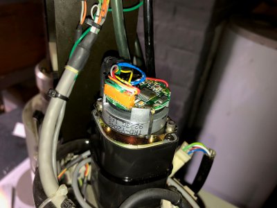
The encoder remains an issue. I did identify it as a Yaskawa TRD-Y2048 encoder (available all over the place online), but I cannot find a manual for it yet. The engineer at Yaskawa did tell me these are factory aligned so I will not be removing it unless it is being replaced.

image010.jpg
 
When I was at Hewlett-Packard in Corvallis, Oregon (mid to late late '80s, IIRC), they used a whole bunch of Seiko SCARAs to assemble calculators. I never worked (played!) with them, but recall they were fun to watch in action. You've got yourself a very interesting project there, macardoso!
 
Is it not possible to directly measure the inductance? or indirectly with an O-Scope?
 
When I was at Hewlett-Packard in Corvallis, Oregon (mid to late late '80s, IIRC), they used a whole bunch of Seiko SCARAs to assemble calculators. I never worked (played!) with them, but recall they were fun to watch in action. You've got yourself a very interesting project there, macardoso!

That's awesome! We have a Fanuc 200iC assembling electrical components near where I work when I have to go down to our factory. I can stand in amazement for an hour at this thing running and nobody else seems interested in the slightest.

Is it not possible to directly measure the inductance? or indirectly with an O-Scope?

I bet it is, but I do not have the knowledge presently to do so. I do have a nice scope that I can borrow if needed. I know the resistance can change by 50% or so from room temp to operating temp, so I wonder what the inductance will do?
 
That is a really awesome machine and I will be following. What is the end game for this? Do you have an application in mind? I am not sure what I would do with this in my shop? Although I like the idea of it making drinks!
Robert
 
That is a really awesome machine and I will be following. What is the end game for this? Do you have an application in mind? I am not sure what I would do with this in my shop? Although I like the idea of it making drinks!
Robert

Thank you! No endgame in mind. I really find robots fascinating and have a bunch of controls equipment to play with. I might set up a work cell and program it to do something silly like draw with a dry erase marker or build legos. I mentioned above but I could build a robotic Auto tool changer for my CNC mill.

Mostly I thought it would be a fun quarantine project to try to dig up information on an old robot, learn how it worked, how it was built, and what electronics they used. I think most people would be stressed out by the missing information I have right now, but it just seems like an adventure. I have a pretty good feeling that I can get this running one way or another.

Plus one day I really want to do the same thing with a 6 axis articulated arm. This would be a great proof of concept. The kinematics and control theory behind those are vastly more complicated than a SCARA.

I might do a couple of posts about servo control and kinematics. Maybe some people will find them interesting if they aren’t familiar with robotics.
 
"robotic Auto tool changer for my CNC mill. " Duh, misinterpreted that.
Could this arm hold a tool like a router and be used as a CNC carving unit? I was thinking if you could carve something like foam you could do awesome lost foam casting. I have seen guys do amazing stuff with that. (GM too!
)
Robert
 
Back
Top