Mike's SCARA Robot

This reminds me of the sticker our lead network engineer has on the back of his monitor "I can explain it to you, but I can't understand it for you".

Awesome work there, especially figuring out the checksum stuff.

John
 
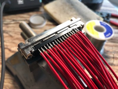
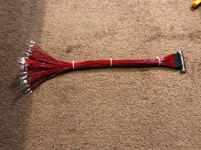
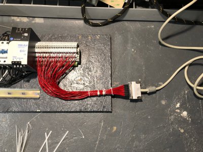
Big progress last night. I soldered up a MDR68 / SCSI68 bulkhead adapter and connected it to the previously shown terminal blocks. This got mind numbingly boring as every step had to be repeated 68 times and the pins were very small, close together, and delicate.

I began soldering from the middle rows outward. I prepped all of the 22ga solid core wires by straightening them, cutting them to length, and stripping the ends to the correct length. I have a pretty good method of soldering that can get good joins in these tight connectors. I dip the tip of the wire in warm liquid flux, tin the end such that there is a slight bulge on the end of the wire, dip the tip in flux again, then use only the soldering iron and the solder on the wire to make the connection. This frees up having to have a hand to add solder. Also the amount transferred is very controlled since you can judge the size of the solder bulge before connecting to the connector. Bridging pins is the big concern here.

image013.jpg

Here was the result after 2 hours of soldering. I love the Weller digital temperature control soldering iron I have. I broke out a brand new very fine tip for the iron to make this easier.

image015.jpg

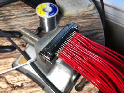
I added a small cut of heat shrink tubing to every wire to avoid shorts where the pins are located. Took almost an hour to get the tubing installed.

image017.jpg

Here was the result after being shrunk with a hair dryer. The whole time I was very nervous of breaking a pin off the back. I could not find this connector with solder lugs so I was soldering to PCB pins. Breaking one pin would ruin the whole cable assembly since nearly every pin is used.

image018.jpg

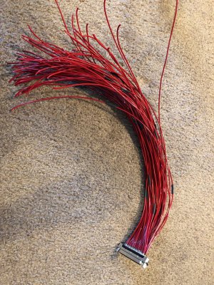
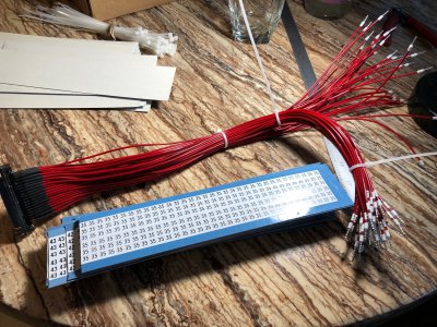
The back of every wire was stripped and had a ferrule crimped on. The ferrules aren't super necessary for solid core wire, but they make it easier to work with the terminal blocks.

image019.jpg

I then had to trace every wire and label it with the appropriate number. I used Brady wire wrap labels at home but much prefer printed heat shrink labels.

image022.jpg

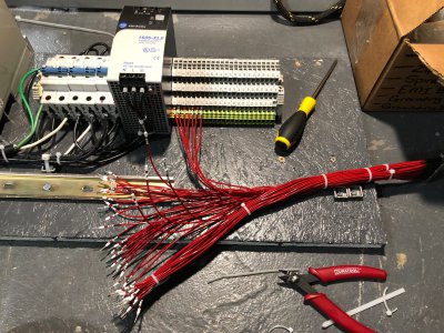
I started to land them on the terminal blocks taking a lot of care to try to untangle them as I went along.

image024.jpg

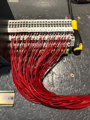
And done!

image028.jpg

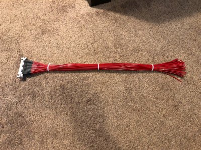
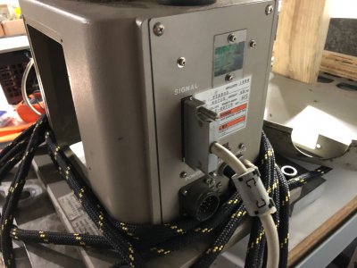
The factory robot signal cable fit perfectly!

image029.jpg

image030.jpg

All together this took 4.5 hours. :bang head:

I hope I never break a pin on this but I'm really worried about it. The outside pins got bent a lot just by working with the assembly. I have everything well zip-tied together to reduce stresses on the pins. I might see if my wife has some clear nail polish that I could use to bond the wires and pins together on the back of the connector. I am not modifying it at this point.

-Mike
 
Last edited:
One other update...

Thanks to the excellent sleuthing work of @brino I was able to figure out that my motors have what is called a "multiplexed encoder". It definitely does commutation. There are A & B quadrature signals and one additional signal C (labeled as the differential pair Z/Z* in the robot manual - I guess just to confuse people). The C signal is some sort of composite of the U, V, W, and Z (hall effect commutation and index) signals. The circuit is pretty straightforward, but there is a Yaskawa proprietary ASIC with no documentation that does the magic to make this composite signal.

Right now I have no idea what that signal looks like or have any other information on it, but it is a start. I have an oscilloscope to check that signal and I'm hoping to have some screenshots to share tonight. There was some mention in a DeltaTau Power PMAC manual that this encoder might present some sort of signal right when it is powered on. Could be serial but I don't think so?

It is disappointing because I cannot use these motors as-is anymore since the Z channel (really the C channel) is not purely an index signal and my drives will fault on bad encoder data. My new hope is that the multiplexed signal is some sort of analog pattern (maybe a 1 cycle SIN/COS wave) that I can use to create a custom go-between circuit board (maybe several analog comparators in series) that can undo the multiplexing of that signal and pass my drives exactly the signals they expect. This would be a fun pivot on the project. If the signal is digital or serial then things get a lot more difficult and I might need to start considering encoder replacement. I *maybe* could design a board with a microprocessor on board to read this kind of data and generate outputs, but that is getting beyond my PCB design experience.

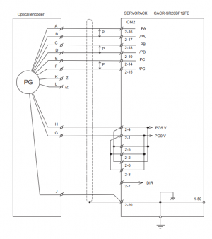
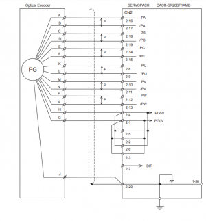
Here are two wiring diagrams from an old Yaskawa servopack manual. The first shows the motor that I have with the multiplexed encoder signal and the second shows a more "normal" incremental commutation encoder with a LOT more wires coming out of it. I would have much preferred to have that encoder.

1589548813969.png

1589548827902.png

Here was the link that brino found that first mentioned the "multiplexed encoder" (it is a bit of the ways down in the product description). This looked to be a 3rd party interface board of some sort.


" Decodes U, V, W, T and Index signals (Option 6) if they are encoded on the C+/C- channels (i.e. Yaskawa multiplexed encoders). Jumper selectable."

"Delta Tau recommends the use of this feature when working with encoders that send power-on information right after the encoder power is applied.(i.e. Yaskawa multiplexed encoders )"
 
Last edited:
Big progress last night. I soldered up a MDR68 / SCSI68 bulkhead adapter and connected it to the previously shown terminal blocks. This got mind numbingly boring as every step had to be repeated 68 times and the pins were very small, close together, and delicate.

I began soldering from the middle rows outward. I prepped all of the 22ga solid core wires by straightening them, cutting them to length, and stripping the ends to the correct length. I have a pretty good method of soldering that can get good joins in these tight connectors. I dip the tip of the wire in warm liquid flux, tin the end such that there is a slight bulge on the end of the wire, dip the tip in flux again, then use only the soldering iron and the solder on the wire to make the connection. This frees up having to have a hand to add solder. Also the amount transferred is very controlled since you can judge the size of the solder bulge before connecting to the connector. Bridging pins is the big concern here.

View attachment 324340

Here was the result after 2 hours of soldering. I love the Weller digital temperature control soldering iron I have. I broke out a brand new very fine tip for the iron to make this easier.

View attachment 324341

I added a small cut of heat shrink tubing to every wire to avoid shorts where the pins are located. Took almost an hour to get the tubing installed.

View attachment 324342

Here was the result after being shrunk with a hair dryer. The whole time I was very nervous of breaking a pin off the back. I could not find this connector with solder lugs so I was soldering to PCB pins. Breaking one pin would ruin the whole cable assembly since nearly every pin is used.

View attachment 324346

The back of every wire was stripped and had a ferrule crimped on. The ferrules aren't super necessary for solid core wire, but they make it easier to work with the terminal blocks.

View attachment 324347

I then had to trace every wire and label it with the appropriate number. I used Brady wire wrap labels at home but much prefer printed heat shrink labels.

View attachment 324348

I started to land them on the terminal blocks taking a lot of care to try to untangle them as I went along.

View attachment 324349

And done!

View attachment 324350

The factory robot signal cable fit perfectly!

View attachment 324352

View attachment 324353

All together this took 4.5 hours. :bang head:

I hope I never break a pin on this but I'm really worried about it. The outside pins got bent a lot just by working with the assembly. I have everything well zip-tied together to reduce stresses on the pins. I might see if my wife has some clear nail polish that I could use to bond the wires and pins together on the back of the connector. I am not modifying it at this point.

-Mike

Very nice work on the connector, having the right iron and technique makes a huge difference:encourage:

One thought for keeping pins from shorting or going open might be to pot the whole thing once you know it's all working.

Maybe something like this?


John
 
Good job on the connector. Been-there/Done-That and it is tedious detailed work. Probably too late to put a larger diameter shrink tube over the bundle to keep individual wires from getting snagged. Still, I suspect that it should be reasonably robust as long as it is protected from repeated mechanical flexing.
 
Been quiet for a few days but have definitely been making progress forward on this project. Mostly focused on those encoders.

First thing I found out is that the wiring table in the Seiko robot manual doesn't match the pinout at my terminal blocks. I'm not sure if I incorrectly labeled my wires (I triple checked this) or if Seiko numbered their connector differently than I did. Long story short is that I will be ohming out every pin before hooking anything up and generating my own pinout chart. No harm in doing that since it is very unlikely anyone will be recreating my work here.

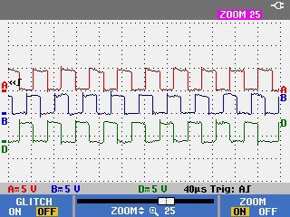
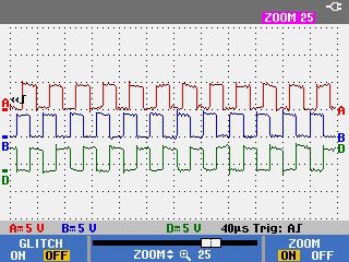
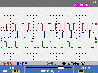
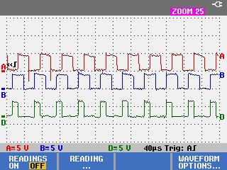
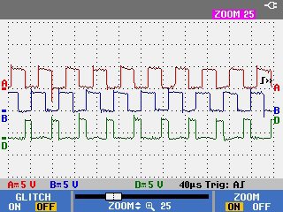
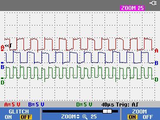
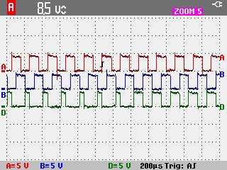
I hooked up a Fluke Scopemeter I borrowed from work to the T2 axis encoder on the A, B, & C channels. I knew from the information in the post above that I had a "multiplexed" encoder. I had all kinds of ideas in my head about what this might look like, but most of them were centered on some sort of an analog signal. I couldn't have been more wrong! Turns out that Yaskawa came up with this super interesting way to encode this third digital channel with a square wave. The "C" channel square wave rises and falls relative to the A & B channels in a total of 6 different patterns. Not surprisingly, this corresponds to the number of valid unique states of normal 3 wire hall effect commutation signals (the kind I am used to seeing on a "normal" servo).

Below are oscilloscope screen shots of the 6 unique patterns. I have named each of them based on their logic relative to the A & B phases. The C channel of the encoder is recorded on channel D of the scope because I liked the green trace better than the grey one of channel C :)

NOT A
NOT-A.jpg
NOT B
NOT-B.jpg
A NOT B
A-NOT-B.jpg
B NOT A
B-NOT-A.jpg
NOR NAND
NOR.jpg
XOR
XOR.jpg

These patterns occur in a very particular order depending on the rotation direction of the motor.

The order goes as follow when channel A leads channel B. This would correspond to a rotation of T2 CCW when viewed from the top of the robot. NOT-B -> A-NOT-B -> XOR -> B-NOT-A -> NOT-A -> NAND

If the direction of the motor is reversed, the signals reverse as you'd expect. In this case, channel B would lead channel A (as shown in the pictures above). This corresponds to a rotation of T2 CW when viewed from the top of the robot: NAND -> NOT-A -> B-NOT-A -> XOR -> A-NOT-B -> NOT-B

These patterns wrap back around to the beginning so in the case of A leading B, NAND would change to NOT-B and in the case of B leading A, NOT-B would change to NAND.

Each pattern is present for 85 periods of either channel A or channel B (340 quadrature counts). This encoder has 2048 lines or 8192 quadrature counts per revolution. This means the full cycle of 6 patterns repeats 4 times or once per magnetic pole pair. I've done a lot of reading on servomotor commutation lately and this was exactly what I expected to see!

The next challenge will be to try to figure out which pattern of pulses corresponds to the appropriate coding of traditional hall effect signals. My intention currently is to try to design a PCB of discrete digital components that can decode this multiplexed signal in real time and convert it into the standard signals my drives are used to seeing. I have very little experience in digital logic design (especially time series logic design) but it will be a really fun thing to try to learn.

If all else fails, I am actively trying to locate replacement motors (AB TLY series) and I have already identified suitable replacement commutation encoders, however each of these have significant issues (mainly cost and the need to completely rewire the robot).

Thanks for following along!

-Mike

Bonus image (Transition between 2 patterns NAND to NOT-B):

NOR to NOT-B.jpg
 
Last edited:
Had one last chat with Yaskawa and got all the remaining motor parameters! They have been so helpful - can't believe it.

With that info I can build four final CMF files to import these motors into Studio 5000 Logix Designer. Here are the possible steps to get these motors/robot running.

  1. Run the motors with self-sensing commutation and no index pulse. This does not require dealing with the multiplexed encoder, but it is likely the drive will not accept either the missing index pulse or the request to do self-sensing commutation. This would be a firmware level issue that I could not fix. Downside is self-sense commutation is less accurate and causes motor motion at startup (up to 60 degrees at the motor shaft )
  2. Run the motors with self-sensing commutation and an index pulse. The index pulse can be obtained by re-wiring the connector inside the encoder and disconnecting the multiplexed channel all together. The drive may still reject the request to do self-sensing commutation. This would be a firmware level issue that I could not fix. Downside is self-sense commutation is less accurate and causes motor motion at startup (up to 60 degrees at the motor shaft)
  3. Design and build a custom circuit board to decode the multiplexed signal and change the CMF files to state that the motor should use hall effect commutation. My drives would ideally have no idea that there was a multiplexed signal at all. The big IF here is designing that board. This is the option I am actively researching because it sounds like the most fun.
  4. Replace encoders with aftermarket commutation encoders. Would cost roughly $250 and require a lot of work to mount and align the encoder, as well as rewire the motor harnesses for the additional wires.
  5. Replace the motors with AB TL or TLY series motors. I have identified semi-suitable replacements which would require shaft adapters. The motors are hard to come by and pretty expensive on eBay (~$1500 for the 4 motors even if I could find what I needed). Perhaps these would turn up at work but unlikely. Again a total rewire of the robot would be required.
  6. Replace the motors with AB MPL series motors. I have better access to these, however they are significantly different dimensionally. I would need to make substantial changes to the motor mounting hardware on the robot including new brackets and shaft adapters. The motors might not fit nicely inside the robot housing. Again a total rewire of the robot would be required.
I have fairly good confidence that I can make either option 1, 2, or 3 to work now. And with the final motor data, options 1-4 are possible. Without that info I would have had to replace the motors entirely.

-Mike

EDIT: Updated on 5/20/2020 to include the option to use the index signal present at the encoder connector but not wired to the robot. Signal is 5V single ended.
 
Last edited:
Spent last night finalizing my understanding of the multiplexed signal coming from these encoders. Using a circuit diagram I managed to find, I was able to identify which pins of the integrated circuits on the encoder PCB corresponded to which Hall Effect commutation signal state. This was important, because I could see what the different states of the signals were before they got multiplexed in the ASIC and compare that to the multiplexed output.
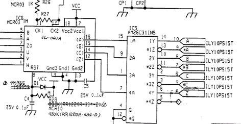
image041.jpg

Using some extremely fine (.002" DIA) magnet wire, I was able to solder to each pin I was interested and plot that signal alongside the outputs from the chip measured at the terminal blocks. This was really tricky because I have no light where the robot is right now so did everything by headlamp, and I had to stand on top of the table to reach the motor. Made it really difficult to do some really fine pitch soldering. No shorts though! I couldn't use any flux due to concerns of contaminating the code wheel. I also covered it in plastic when I was not soldering to keep dust out.
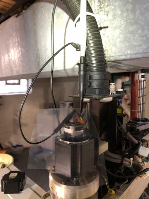
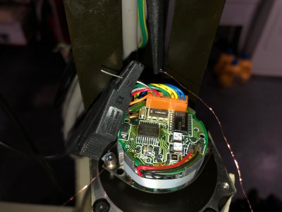
image042.jpg

image047.jpg

And a super close up showing the wire soldered to pin 2 of the Yaskawa JL-041A ASIC.
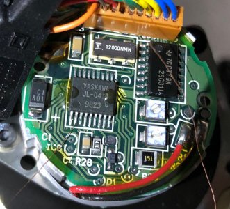
image051.jpg

Here is what I found. All images show channel A leading channel B. Applicable Hall Effect signal is shown as the black trace.

When scoping pin 3 (Hall Channel U), the multiplexed signal could be seen transitioning from NOR to NOT B as channel U rose.
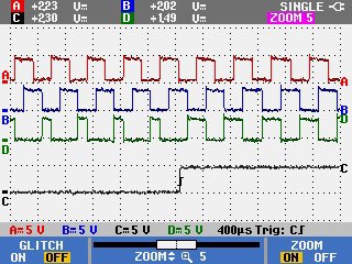
IMAGE022.jpg

The multiplexed channel could be seen transitioning from XOR to B NOT A when the channel U fell.
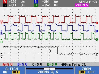
IMAGE023.jpg

When scoping pin 2 (Hall Channel V), the multiplexed signal could be seen transitioning from B NOT A to NOT A as channel V rose.
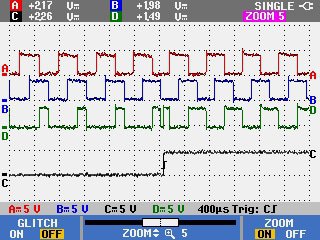
IMAGE016.jpg

The multiplexed channel could be seen transitioning from NOT B to A NOT B when the channel V fell.
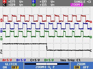
IMAGE017.jpg

When scoping pin 1 (Hall Channel W), the multiplexed signal could be seen transitioning from A NOT B to XOR as channel W rose.
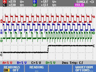
IMAGE013.jpg

The multiplexed channel could be seen transitioning from NOT A to NOR when the channel W fell.
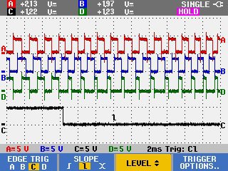
IMAGE014.jpg

I also scoped the Z0 signal (Index signal) and compared it to the multiplexed signal. The Z0 pulse only occurs once per motor revolution, or once every 4th set of multiplexed patterns. The index pulse comes across as an extra long high state near the end of the XOR pattern where it transitions into B NOT A.
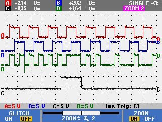
IMAGE027.jpg

The pattern is nearly identical in the reverse direction (Channel B leading Channel A) but slightly different.
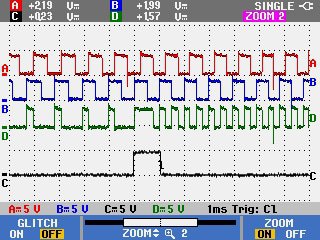
IMAGE026.jpg

Additionally I was able to confirm that the Z index signal is available (not multiplexed) on pin 4 of the encoder. Yaskaw did not land a wire on this, but it does leave the option for me to rewire the connector to ignore the multiplexed signal, transmit the Z index pulse to the drive, and use self-sensing commutation. You can see the un-pinned slot in the connector where the index pulse is present.
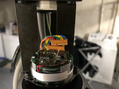
image049.jpg

Thanks to this information, I was able to build a full timing diagram of the encoder signals and multiplexed patterns. I am using this to write a specification for a digital circuit to decode the pulse stream. It is a lot more complicated than I expected and requires knowledge of the current and past 3 states of all signals after each quadrature count. I am not a member on any electronics forums, but I intend to ask for help evaluating the feasibility of this circuit on those forums.
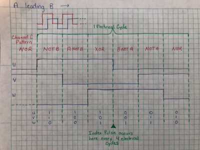
image050.jpg

I should probably try running a motor with self-sense commutation soon, but I am enjoying decrypting the secrets that Yaskawa packed into their ASICs and trying to learn enough about digital circuits to decode this signal back to the original signals.

-Mike
 
Back
Top