An Electronic Lead Screw controller using a Teensy 4.1

I have been seriously thinking about this. I have DRO inputs on my ELS. Still haven't worked out how to do stops for threading, but feeding should be straight forward. Was toying with how the display would look, and behave for this function, but haven't gotten serious about it yet.

All of this would be a little bit easier, once I get all the loose bits put in a box or two! Once I receive my PCB's I will put a bit more thought into going to a stop. It may require a respin, so I need to think things out a little bit better. The turn time for a PCB is rather long, especially if you are not willing to pay for rush service and delivery.
If you work out stops for threading let me know. Why slow brain can't quite figure out how to keep the timing for that, but that would be an awesome feature.
 
If you work out stops for threading let me know. Why slow brain can't quite figure out how to keep the timing for that, but that would be an awesome feature.
Unlikely that my brain is any quicker than yours. It's not a trivial problem. Every time I think I fully understand threading, I am proven wrong. I have a glimmer of what to do, but honestly, no plan yet.
 
Tried an experiment to avoid switching micro step values on the stepper motor driver. My CL57T can only change the micro step setting via a DIP switch. So I set the driver to micro step = 4 and redid all my tables. Now I can do 4 TPI threads.

So I tried it. Yeah, well the stepper has twice as much torque, which is good. I tried to stall it and it was a lot harder to stall out. It is a bit noisier with 4 than at 8. There's sort of a whine, at least when cutting 4 TPI.

The lead screw is really going quick! So I chucked up a piece of 3/4 12L14, because I had a 3/4" collet in there. You know how this is going to turn out. The deeper you go, the less rigid the part is, especially if you picked a 3/4" diameter piece and were cutting 4 TPI threads. There was a bit of chatter, and it was getting late, but I think this is a success. To know for sure, I will attempt a larger diameter part. The thread pitch gauge was right on the money, so that was good. My lathe was at minimum speed, 100 RPM, and the thread wheel was going rather fast for this beginner. Missed a couple of times, but caught them before cutting.

I will try a couple of other threads to see if there's any issues. Still not sure if this is a keeper solution or not. Not sure if my lathe is really rigid enough to do 4 TPI justice. Still it was a fun experiment for the evening.
 
Might leave things at 4 micro steps. Definitely torquier. 4 TPI threading is an adventure though. I will need to make a new pulley if I want to do this, 100 RPM is fast at 4 TPI. 50 would be a bit more comfortable. Not sure how I would do that, but, I will look into it. That test piece 3/4" 12L14 was seriously undersized, there was deflection and you could hear the spindle and stepper grunting their way through the steel. Higher values of TPI seem to be ok.

Think I will amend the tables to leave 4 TPI out. That only means that I commented them out of the code. If I wanted to, I could uncomment them. Likewise, 8mm and 10mm pitches. I don't even have a threading tool that wide.

I can't wait for the PCBs to show up. My JLC boards have made it to the Chinese airport. The PCBWay ones seem to have delayed tracking, the last date they show is two days ago.

There is a serious noise problem, perhaps related to the power supply, or a ground loop of some sort. If I attach a scope probe to observe signals, connecting the ground of the probe to the interface board causes a very large rise in noise spikes. This noise is everywhere and coupling to everything. The impulsive noise is causing ground bounce. Just attaching the probe ground can cause the noise to falsely start the motor in the opposite direction, or cause it to chatter. Pretty impressive, but sadly not what I want or need. The interface board and the micro controller are only attached through teeny little jumper wires. The interface board was only proof of concept - there's no ground plane or decent decoupling. So I know that it is a classic "bad implementation", but have to suffer through it a little while longer. I have tried having all the power come from a common power strip, or different electrical circuits. If anything, using a common power strip for the oscope, stepper motor and Teensy is far worse than putting the stepper power and Teensy on different grounds.

On the good side, my Bud boxes should be here tomorrow. Also a Power inlet Module IEC with fuse and power switch, and a matching power cord and some miscellaneous components. Connectors seem to be moving, somewhere or another through China. As long as they are progressing, I'm happy.
 
There is a serious noise problem, perhaps related to the power supply, or a ground loop of some sort. If I attach a scope probe to observe signals, connecting the ground of the probe to the interface board causes a very large rise in noise spikes. This noise is everywhere and coupling to everything. The impulsive noise is causing ground bounce. Just attaching the probe ground can cause the noise to falsely start the motor in the opposite direction, or cause it to chatter. Pretty impressive...

So, since you are building pretty much the same thing I was planning on building, would you possibly be interested in some form of collaboration? My day job is circuit design, and circuit board layout. I do switching power, RF, analog, digital design for harsh environments. Everything from small SMT board with 0402 components, to big stuff with bolt terminals. PM me if interested.

As for noise, planning on upgrading this lathe to a VFD. So yeah, that's a concern. Just yesterday ordered some encoders with RS422 (differential) outputs. I've got a few RS422 to logic output IC's picked out...

Dan
Possibly to very interested.

Stubborn guy that I am, will at least wait for my PCB to arrive! My PCB has ground and power planes, so it ought to help. Local and bulk decoupling. Not using a crappy wall wart of any kind ought to help as well. I can cobble in a linear regulator as a test if need by. My PCBs are due to arrive in early October, via the "slow boat", aka the cheapest and slowest shipping I could get from China. A set of boards made it to the airport, so it shouldn't be too, too long.

My background is (was) automotive radar. So millimeter wave RF, SMT, 0201 components, extreme tolerances and dense packaging were normal and required. Also did some EM modeling of those systems. Assisted in whole car level EM simulations for a while. As an aside, that was a sheer exercise in high performance computing with massively parallel GPU's solving EM equations.

My G0752Z lathe is powered by a VFD from the factory. From my simple experiments, it appears that the VFD is not the culprit. The problem exists without the VFD on. The problem does not get worse if the VFD is active. The issue's more likely grounding and power supply noises. The extent of the problem follows where the power cords are plugged in. The motor power supply line is way longer than required, I am sure it is radiating and conducting junk everywhere. There is no cable shielding at the moment. Haha, nearly everything is wrong, but it still works as an ELS - as long as I don't connect the scope probe to ground. Today I received some Bud Boxes, but I still need for my connectors to arrive from - yes, China. Only one's that I could find at a palatable price. I have no access to nice Amphenol Mil-spec connectors. :(

Differential lines are great, so is optical coupling. The interface to my stepper driver is opto coupled. I'm positive my design could be a lot better. My PCB was designed as a prototype, just to get an idea of what to expect. At V0.1, if it is reasonably functional, and a little less noisy, I'd consider it a successful run. Already have some ideas for improvements, most of which I should have put in the first time, but I was getting too impatient.
The second spin ought to be a whole lot easier, since I won't have to learn the tools from scratch. Last time I personally designed PCB's was the last millennia, the 1980's to be exact. So I had a lot of catch up to go through for this board! Was a big change for me to go from Unix workstations, auto-routers, and Parts Departments (groups of people dedicated to making footprints and symbols), an procurement, to a PC with open source SW, rolling my own parts & footprints, and ordering stuff on my own. Wasn't hard, but it sure was a lot to learn and do in a week and a half.

Don't have a day job anymore. Was downsized a while back, and decided working and playing for myself was more interesting. The only deadlines I have are the ones I make for myself. So I get to apply myself to pursue these daydreams. :) My day job kept me so busy I had little time for fun.
 
Possibly to very interested.
...
Don't have a day job anymore. Was downsized a while back, and decided working and playing for myself was more interesting. The only deadlines I have are the ones I make for myself. So I get to apply myself to pursue these daydreams. :) My day job kept me so busy I had little time for fun.
Yeah, just let me know.

I picked up on the fact that you had a pretty good technical background. Wasn't sure what, but the telltales were there! :)

I'm going to slowly keep plugging away on this design either way. Mostly because I've been threatening to learn Arduino/Teensy for a while, this is a good an excuse to start. As you mentioned, time is always the challenge. My problem is learning the tool chains and code libraries for anything new. I do a lot with microchip PIC24/dsPIC3x platform, which is nice for many things. But the Teensy has a lot of advantages for other things.

Circuit board stuff isn't hard. But like anything, it takes time to become proficient at.

My ultimate goal is a pretty high end ELS and feed drive. (Not CNC! There are several high end CNC controllers with 3Ph servos sitting just feet from the lathe!). This 1940's Sheldon lathe was just rebuilt (actually I pick it up in a few days), with all sliding surfaces machined and scraped, head stock and tail stock aligned, etc. I'm after a 'tool room' tight lathe without having to buy a Hardinge HLV-H. The cost of higher end parts (encoders, servos...) are minor in comparison to the rebuild, so don't mind buying the 'better' parts.

That said, the controller with teensy and screen should be pretty inexpensive overall, even if done well with good parts. If we can work together and you could benefit from my labors, all the better!


Dan
 
Haven't had any pictures in a while. So I will add a few. There's been little progress, but might as well add some pictures...
PXL_20220923_190156052.jpg
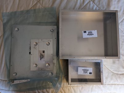
The Bud boxes. A 5x7 and a 10x12. The Teensy PCB and display go in the 5x7, which will sit on top of the lathe. The 10x12 will house the motor driver and the driver power supply. Waiting for connectors...
PXL_20220923_191909804.jpg
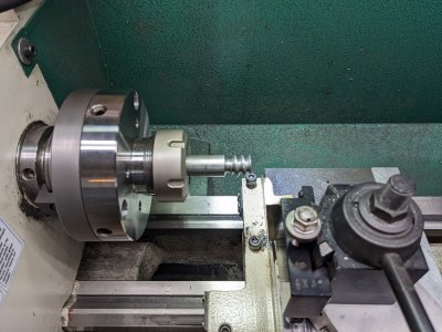
My first attempt at 4 TPI. Dope that I was, the rod diameter was too small. Serious deflection of the rod. But it is 4 threads per inch.
PXL_20220923_192055773.jpg
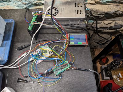
The mess of stuff that cut that thread. White, solderless breadboard with the Teensy, green board with interface circuits, red board with the 3.2" touch panel display, stepper motor driver near the top, standing on edge, and the stepper motor power supply in the back.
PXL_20220923_192145788.jpg
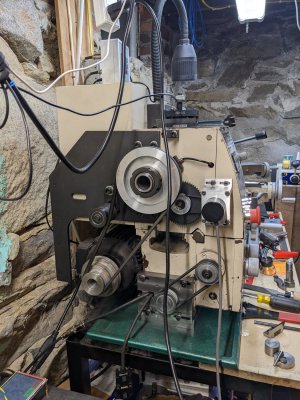
The lathe with cables and belts and encoders and cables hanging every which way. Every time I fire this up, I do a check and tie back any cables. I will be glad to button this thing up!
 
Yeah, just let me know.

I picked up on the fact that you had a pretty good technical background. Wasn't sure what, but the telltales were there! :)

I'm going to slowly keep plugging away on this design either way. Mostly because I've been threatening to learn Arduino/Teensy for a while, this is a good an excuse to start. As you mentioned, time is always the challenge. My problem is learning the tool chains and code libraries for anything new. I do a lot with microchip PIC24/dsPIC3x platform, which is nice for many things. But the Teensy has a lot of advantages for other things.

Circuit board stuff isn't hard. But like anything, it takes time to become proficient at.

My ultimate goal is a pretty high end ELS and feed drive. (Not CNC! There are several high end CNC controllers with 3Ph servos sitting just feet from the lathe!). This 1940's Sheldon lathe was just rebuilt (actually I pick it up in a few days), with all sliding surfaces machined and scraped, head stock and tail stock aligned, etc. I'm after a 'tool room' tight lathe without having to buy a Hardinge HLV-H. The cost of higher end parts (encoders, servos...) are minor in comparison to the rebuild, so don't mind buying the 'better' parts.

That said, the controller with teensy and screen should be pretty inexpensive overall, even if done well with good parts. If we can work together and you could benefit from my labors, all the better!


Dan
If you figure out how to use the HW encoder library with 3 or 4 inputs, that doesn't interfere with the display, and other stuff, I'd like to know. I ended up using luni's EncoderTool for an interrupt driven SW encoder. I have tested it to 400kHz, so it is pretty good. This is the equivalent to almost 3 times faster than my chuck is rated (2000 RPM).

I am also connecting my DRO's to this board. I'm using the same EncoderTool for the DROs. Really makes that part easy. For servo control, I am afraid you are on your own. I am only using a closed loop stepper. I could already see where a servo would be better, but honestly, I think it is overkill for a small 10 x 22 lathe. Not planning to cut 4 TPI threads on this machine, just yet. To do so, I need more torque from both the spindle and stepper. A more rigid lathe would be helpful, but a 10 x 22 is what I have now.

I'd be interested in a slightly bigger display that is 480x320 and is still SPI based. Shoehorning everything on this 320x240 is possible (I did it) but it is limiting. Started learning about the lvgl library to get some nicer displays. Just got an example to compile, which is a first step. My UI needs work, but is completely functional, but still could be a bit more pleasing to the eye. Hope that the lvgl library will improve the look and feel.
 
Thanks for posting the images. Looks good! The 4 TPI thread looks good too.
I'd comment about exposed leads, but you know that stuff already! :)

Is that a mining town poor rock stone basement? Looks just like the one I used to have a shop in!

If you figure out how to use the HW encoder library with 3 or 4 inputs, that doesn't interfere with the display, and other stuff, I'd like to know.
That's one of my first goals. I have some adafruit level shift modules coming, once they arrive testing the encoder hardware can start. Been reading up on that hardware as time permits, and it appears there are some libraries to handle it already written. But the details are still fuzzy.

...I have tested it to 400kHz, so it is pretty good. This is the equivalent to almost 3 times faster than my chuck is rated (2000 RPM).
For this chip, I think the limiting factor may be the Interrupt latency. Quick test last night with an interrupt on an external pin and ran it with a signal generator. If the interrupt code is short (toggling a pin) it would handle 2.5Mhz interrupt rate. However it appears a majority of that time is actually the interrupt latency. At 600Mhz it was 108nS, or about 64 clock cycles give or take! Probably not an issue at 600Mhz, but running three or four encoders in software might push things a bit.

My hope was to include the liner scale DRO's in the design also. In my mind it would be nice to use the linear scale as position feedback, to trim the servo (or stepper) position in case there is any lead screw error. Not control it, but just nudge it as necessary to keep it on track.

That and a few other hair-brained ideas I have in mind... :)

There are servo drives that use the same step and direction inputs just like the stepper drives. Clearpath is one option, but others exist. My main reason for servo over stepper is to reduce vibration, avoiding the resonances of steppers. Micro stepping helps, but doesn't completely eliminate it. Servos have their own issues, but from what I've seen are much less noisy.

Anyway, It'll take a while to get up to speed with this Teensy. I'll keep you posted if I learn anything interesting...
 
Back
Top