[How do I?] 110v to 220v change

DavidR8

H-M Supporter - Sustaining Member
Staff member
H-M Platinum Supporter
Joined
Oct 16, 2019
Messages
6,573
I’d like to change the voltage over on my mill so that I don’t have to run a 20A 110v circuit.
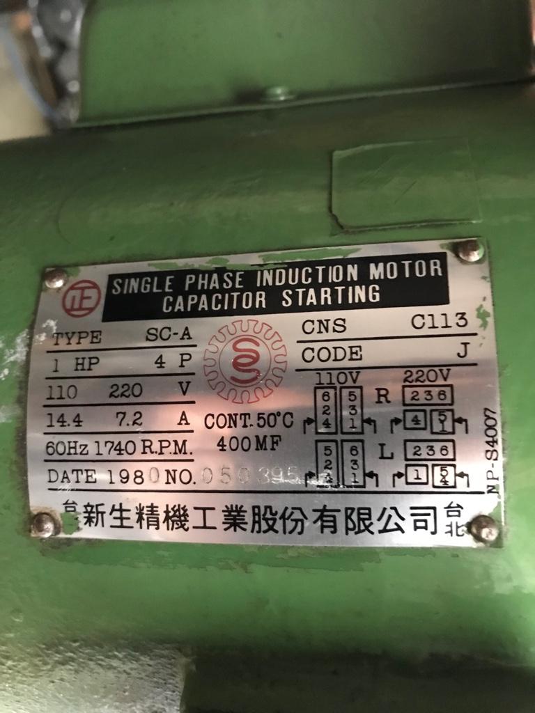
This is the motor data plate.
77fa88b25a3d01001ba26f300a4b7029.jpg


And this is the wiring enclosure.
791f409539f0e87f2274110c34c723b7.jpg


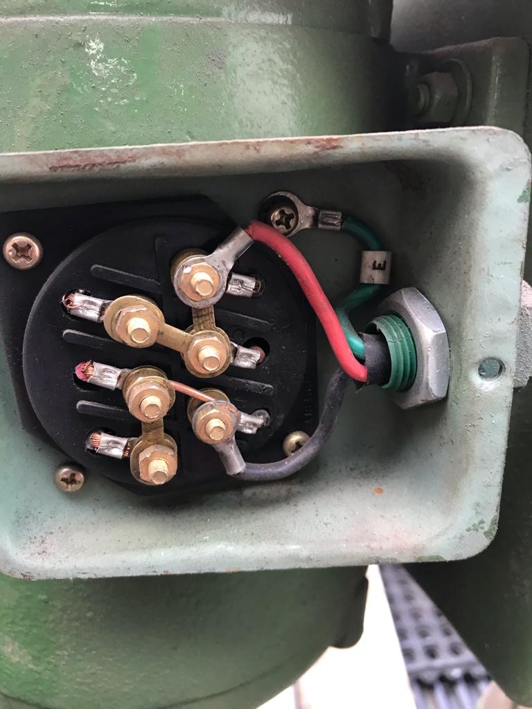
I cannot make any sense of this diagram as it relates the the current configuration.
Any help is greatly appreciated :)


Sent from my iPhone using Tapatalk
 
The piece of copper wires suggests that someone has already been in there and messed with it. I'd ignore the current setup and follow the diagram for 220v and the rotation you're looking for.
 
I would have a licenced electrician do it, the smoke is just waiting to jump out of the wire, and escape. :)
 
I don't know how to figure this one out. There doesn't seem to be any identification on the wires. It's obviously working, so we can assume that the black wire is connected to some 3 wire combination per the data plate, and the red wire is connected to the other. But at the moment, that's all we know.

Unless you can find some numbering on the motor wires, this is going to be a tough one. Maybe Mike has some ideas.
 
the motor is wired for 110v operation right now

all you need to do is to take the ROUND copper Jumper OFF (you won't need the jumper anymore), and then move the jumper from the top LEFT, to CENTER
if it runs backward, take the CENTER jumper on the RIGHT side and switch jumper position to have the CENTER connect with the LOWER stud instead of the UPPER stud
 
Last edited:
The Doctor is In....
How in the devil did you figure that one out?
I just pasted the images into a draw program, and tried figuring it out.
I failed. Heck I still can't figure it out. That diagram is worthless... To me at least...
the motor is wired for 110v operation right now

all you need to do is to take the ROUND copper Jumper OFF (you won't need the jumper anymore), and then move the jumper from the top LEFT, to CENTER
if it runs backward, take the CENTER jumper on the RIGHT side and switch jumper position to have the CENTER connect with the LOWER stud instead of the UPPER stud
 
here is a picture of how it would look , i added pixelated red jumpers to illustrate their positions for 220v operation

Untitled.jpg

if i'm correct, the motor will turn in the correct direction.
if the motor runs in reverse direction, move the jumper from T4,T5 and move it from T4 to T1
 
Last edited:
The Doctor is In....
How in the devil did you figure that one out?
I just pasted the images into a draw program, and tried figuring it out.
I failed. Heck I still can't figure it out. That diagram is worthless... To me at least...
the diagram on the motor is cryptic, at best.
through osmosis, i was able to infer the motor connections from the 220v connection diagram
positions 1 and 4 did not change, whereas the other connections did change between 220 and 110v operation.
 
Back
Top