2019 POTD Thread Archive

I am about 50% done with some bomb proof hinges for the belt cover on my mill. The pot metal ones it came with broke once so I made steel replacements for the parts that broke and now the other half broke so I said screw it, the steel ones on it were 1/8" thick so I got a piece of 3/8" bar and started making hinges that will likely be strong enough to lift the rest of the mill with. OK maybe that is an exaggeration, but they will certainly hold the weight of the aluminum belt cover and the 10 pounds of bondo covering it. I found some hardened steel pins from bow axles in my junk box. I will need to track down some e clips for the ends but I know where I have some of them. at work.
 
Job was to make a differential screw for a qctp knurling tool I'm working on. Actual part is a 4" 3/8-24 threaded rod with 2" of LH thread and 2" of RH thread. I cut the RH thread first which was on the tailstock end. Ran I die over it because I had one and it guaranteed fitment. The tricky part was I couldn't check the LH threads until it was parted. I ended up gauging my thread tool with the completed RH threads to get my final number and went with that. Parted when finished and what ya know she fits. Last to do is either hex the end or I'm thinking of broaching a hex in the end but that means I would have to build a rotary broach to finish.
image.jpeg
 

Attachments

  • image.jpeg
    image.jpeg
    1.6 MB · Views: 28
  • image.jpeg
    image.jpeg
    1.5 MB · Views: 26
Hmmmm ... now you've got me thinking ... why not use different thread pitches on the RH/LH screw? Buy whatever LH die is cheapest, then use the "other" (UNC vs UNF) pitch on the RH end. For instance, ⅜-18 and ⅜-24 would combine to make what's essentially a 72 TPI effective pitch. This might well be the way to make a simple scissors knurler that's as easy to tighten (though not as quick to adjust) as a camjack style.

If you start to smell smoke, that'll be my brain working ;)
 
I messed around with my 2x27” belt grinder trying to get the belt tracking to work better.
Took some fiddling but managed to get it working right.
Not exactly a high quality piece of equipment


Sent from my iPhone using Tapatalk
 
Finally made a bit more progress for my powerbrush project (mating a Bercomac 48" Brush attachment to a Husqvarna 52" hydro walkbehind mower).

I had worked for some time on making a lever for raising/lowering the brush from the operators position, and was mostly done when I noticed that the system interfered with the rotation of one of the front wheels, and to rework it so it didn't interfere would require a more complicated multi-rod setup which would be more difficult to get right (for me, at least), and I also realized that using a physical lever would be pretty annoying to use, as you have to lock the hand-controls on the mower, work the lever, then unlock the controls and start working/moving again.

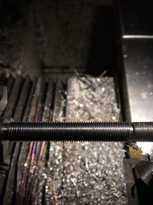
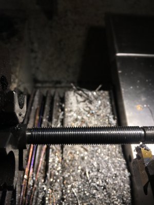
So, I discarded those bits, bought a 2k lb 4" electric actuator, and made an adjustable mount for it, as I'm not entirely sure of the range of motion I should use for raising the brush (as raising it too far may cause the belt driving the brush to stretch or possibly break if it's raised too far). I was also concerned with possibly damaging the actuator from something hitting it (such as a curb, or the edge of a trailer ramp). So, I made a setup that lets me adjust both ways using clevis joints on threaded rods.

Behold (note, it's upside down, the brush attaches to the bracket that the right side of the actuator is attached to):
IMG_1528.jpg

Now I need to work on the electrical wiring to test it out a bit. I think this will be pretty solid, the only bit I'm concerned about is the center rod holding everything together on the left side of the actuator. It's a 1/2" rod (limited by the side of the hole the actuator has), and most of the force of the actuator will be through the two threaded rods on each side of it (there's another rod on the other side of it), and the distanced between the threaded rods and the actuator may result in that center rod bending. But, that's something I'll deal with once I get it working and test it out.
 
Well, this is a good news/bad news post.

I installed the unit in the previous post to the Husqvarna, wired up a DPDT momentary switch to control it, and it does raise and lower the brush nicely, perhaps a bit slowly, but it's not terrible. No side of any bits bending, but it does have the ability to lift the brush too high (at least, I think it's likely too high for the belt to not break), so I'll have to watch it. Or maybe add a limit switch.

I did get a little too cute with how the actuator connects to the bracket that the brush mounts to (seen at the upper right corner in the pic of the above post). I made it so it's solid when the actuator is extending, but when retracting, it can give a little. But, while testing raising/lowering the brush, that "give a little" part didn't work quite right, and it resulted in the shiny silver part holding the actuator's rod being pushed away from the main body of the unit. Broke off the tab on each side, and it's slightly separated (held together with a clamp for no particular reason in the pic):

IMG_1529.jpg

The actuator still functions (yay), so I'll fill the two holes in the case with some rtv so water & dirt doesn't get in there, and make a clamp around the housing to hold it together, and see how that works. As well, I rejigged the mount so that particular problem can't happen again, but it also won't have that free play. Once everything is operational, I'll see how it works, and if I can leave it as-is, or if it's better to have that free-play in the setup and come up with another way to have it...
 
Finished up making my version of a qctp knurler. I had been wanted to make a new knurler because I never had any luck with my Armstrong bump style knurler.
I didn’t have any type of prints all on the fly measurements which I ran into alittle glitch. Actually two first was the dovetail lock screws on knurler dovetail. I barely had enough room for the 10-24 screws. The counterbore for the heads didn’t have enough room. Works as it should but a design flaw. Second was the mounting screws for the knurling block to the qcth. I first had drilled and tapped the holes in the qcth. Went to drill and counterbore the knurling block and found that the counterbore on one side of the dovetail block would hit the dovetails when I went to counterbore. The through hole had about .020 clearance to edge of dovetail. Well one side was good and one side needed to holes moved in. I ended up moving the hole in and centered using a 3/8 bolt on that sideverses two 1/4-20 screws
Worked out good just disappointed I didn’t catch it prior to laying out bolts.
I tried it out and it seems to be night and day difference from a bump style Knurler. After testing different style wheels I had to make some knobs for the knurling tool. Did some straight and diamond knurling in different metals I’m very pleased with the outcome.
B86C8381-535A-4DA4-86D5-13A06CFF6C3F.jpeg039878C5-AF0C-42D6-9C5D-D821AF662589.jpegDBDC21D4-DD10-47B7-ADE4-B8AE0D885AA2.jpegD6ED9E3D-F0CB-4509-B6B6-3F6003AB4A9C.jpegCFBCE706-5F20-4E84-9B91-3142F2FCB9D7.jpegCBD9B4AE-666E-420E-BBBF-912FEDFE2CF7.jpeg
Thanks for looking!
 
That looks great, Cadillac. I think I'm starting to like these sliding designs better than the scissor style, not sure why though. Maybe they seem more compact or less prone to racking, don't know. One of these days I'll tackle one...

-frank
 
Back
Top