

-
Welcome back Guest! Did you know you can mentor other members here at H-M? If not, please check out our Relaunch of Hobby Machinist Mentoring Program!
- Forums
- THE PROJECTS AREA
- PROJECT OF THE DAY --- WHAT DID YOU DO IN YOUR SHOP TODAY?
- Project of the Day Mega-Thread Archives
You are using an out of date browser. It may not display this or other websites correctly.
You should upgrade or use an alternative browser.
You should upgrade or use an alternative browser.
2019 POTD Thread Archive
- Thread starter GoceKU
- Start date
- Joined
- Mar 26, 2018
- Messages
- 8,410
I finished a static wheel balancing stand today. Made entirely from inventory on hand (4 skate bearings, a short length of rectangular aluminum tube, some 1018 round bar, etc) I’m actually surprised at how sensitive it is.
The bearings are only ABEC-3 so really not precision by any stretch, and although my wheels turned out very uniform they’re not hardened nor ground. Still, when I mounted a used 5” wheel it easily responded to differences in fractions of a gram. I don’t know what a “real” balancer resolves at, but I’m pretty happy with this. I also lucked out and had a beautiful polished 1/2” shaft (electronics salvage) that was 1/2” and not a metric diameter so that counts for a lot I think.
Anyway, thanks for looking.
-frank
View attachment 309040
View attachment 309041
Francist,
Did you make the wheels? or buy them. I can't tell by the pic.
I would also like to make one of these.
Can you show us a pic of the wheel bushing breakdown? Close ups of the wheels?
Thank you
- Joined
- Sep 5, 2013
- Messages
- 3,207
Hey Jeff, I made the wheels.
I’m afraid I don’t have more in-progress photos, this really wasn’t a complicated project. I had the skate bearings (roller blade bearings, ABEC-3 which are the cheapies) that are 608ZZ so 8mm shaft size, 7mm wide I think, and 22mm OD. You can look up those numbers to make sure, I convert everything to inch when I work so I may have got one sideways.
The wheels started out as 2” 1018 bar that I took four pucks off of and went from there. Here’s my checklist (I do these lists on my phone sometimes when I’m watching TV and thinking about my next operations), but just be aware it’s in reverse order now because I’ve completed all the tasks if you know what I mean. iPhone puts the ticked item at the bottom of the list when it’s done, so the completed list is backwards from the way I completed it. You’ll see what I mean, just start from the bottom.

Here’s a couple close-ups of the mounted wheels and bearings. I aimed for a light press fit in everything but ended up closer to slip fit with a bit of threadlocker. I also bushed the 8mm shaft bore to a press fit for the #10-24 button heads using a bit of acetal I had lying around. An 8mm bolt would have been way too meaty for the application.


There is a very small crown to the wheels in addition to the tapered sides. The wheel ODs are 1.875” with a 10 degree taper each side leaving about 50 thousandths in the centre to accept the crown by hand file after. Total wheel thickness is 0.275” at the hub.
I derived the wheel spacing (to get the overlap) from looking at a picture of a Sopko balancer and extrapolated from that. With my wheels of 1-7/8” diameter, the wheel spacing ended up being 1.1895” which I rounded to 1.2” for the actual build. I don’t know that it’s terribly critical, but I could do it easily so I did. This is typical of the planning detail I went to on this project... . As you can see, it’s very advanced")

The critical thing in my opinion is the accurate preparation of the stub arbor and order of operations at the lathe. Because you cannot unmount the stub arbor without losing accuracy, be certain you have any spacers, washers, etc turned before starting the arbor. Otherwise you’ll lose your concentricity if you need to take the arbor out before you’re done all the wheels.
And that’s pretty much it. If you need or want any other details / dimensions just let me know. I’d be happy to give you anything else you need.
-frank
I’m afraid I don’t have more in-progress photos, this really wasn’t a complicated project. I had the skate bearings (roller blade bearings, ABEC-3 which are the cheapies) that are 608ZZ so 8mm shaft size, 7mm wide I think, and 22mm OD. You can look up those numbers to make sure, I convert everything to inch when I work so I may have got one sideways.
The wheels started out as 2” 1018 bar that I took four pucks off of and went from there. Here’s my checklist (I do these lists on my phone sometimes when I’m watching TV and thinking about my next operations), but just be aware it’s in reverse order now because I’ve completed all the tasks if you know what I mean. iPhone puts the ticked item at the bottom of the list when it’s done, so the completed list is backwards from the way I completed it. You’ll see what I mean, just start from the bottom.
Here’s a couple close-ups of the mounted wheels and bearings. I aimed for a light press fit in everything but ended up closer to slip fit with a bit of threadlocker. I also bushed the 8mm shaft bore to a press fit for the #10-24 button heads using a bit of acetal I had lying around. An 8mm bolt would have been way too meaty for the application.
There is a very small crown to the wheels in addition to the tapered sides. The wheel ODs are 1.875” with a 10 degree taper each side leaving about 50 thousandths in the centre to accept the crown by hand file after. Total wheel thickness is 0.275” at the hub.
I derived the wheel spacing (to get the overlap) from looking at a picture of a Sopko balancer and extrapolated from that. With my wheels of 1-7/8” diameter, the wheel spacing ended up being 1.1895” which I rounded to 1.2” for the actual build. I don’t know that it’s terribly critical, but I could do it easily so I did. This is typical of the planning detail I went to on this project... . As you can see, it’s very advanced
The critical thing in my opinion is the accurate preparation of the stub arbor and order of operations at the lathe. Because you cannot unmount the stub arbor without losing accuracy, be certain you have any spacers, washers, etc turned before starting the arbor. Otherwise you’ll lose your concentricity if you need to take the arbor out before you’re done all the wheels.
And that’s pretty much it. If you need or want any other details / dimensions just let me know. I’d be happy to give you anything else you need.
-frank
- Joined
- Nov 19, 2014
- Messages
- 991
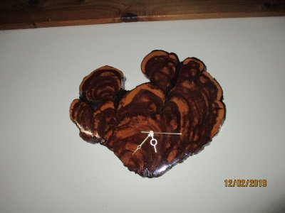
Here's a clock that I built from a slice of a 229 year old (I counted the rings) cedar tree. The interesting thing about this piece is that it didn't grow round, like a normal tree, this one grew in a fan shape, and it has a lot of interesting features in the grain that the camera doesn't show. When I machined the pocket in the back for the clock works the chips came out as a powder, and it gave off a rich cedar scent.
Attachments
- Joined
- Oct 16, 2019
- Messages
- 6,585
Used the new lathe to make two tiny dowels to splint a chicken leg.
Managed .01 tolerance one to the other though so that is saying something.
I’m not sure this even counts as a project.
Sent from my iPhone using Tapatalk
Managed .01 tolerance one to the other though so that is saying something.
I’m not sure this even counts as a project.
Sent from my iPhone using Tapatalk
Last edited:
- Joined
- Nov 19, 2014
- Messages
- 991
I'm not even going to ask why, but yes it counts as a project in my book.Used the new lathe to make two tiny dowels to splint a chicken leg.
- Joined
- Nov 19, 2014
- Messages
- 991
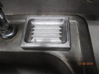
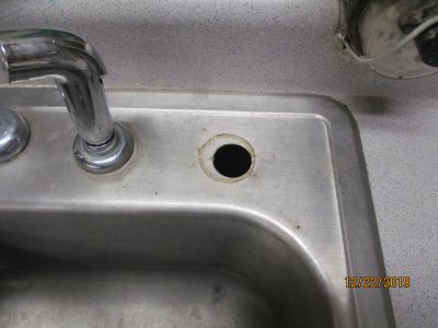
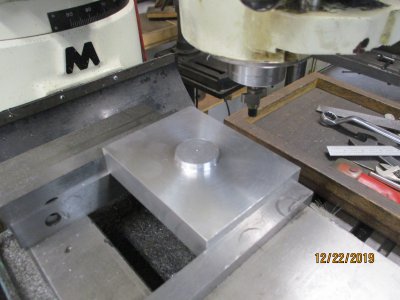
Every shop needs a billet aluminum soap dish, I wanted one that would be held in place by the hole in my sink and easy to clean. I cut out the perimeter with a 3/4 in ball end mill and the grooves with a 1/4 inch ball end mill. I used a carbide router bit to round off all the corners and rubbed everything down with 120 emery. The pin on the bottom was cut on the lathe. I'm thinking of adding two rare earth magnets to help hold it down, so, would the pole orientation matter? I'm thinking magnetic field through the sink and aluminum dish, or am I over thinking it?
Attachments
- Joined
- Oct 16, 2019
- Messages
- 6,585
I'm not even going to ask why, but yes it counts as a project in my book.
We woke to one of our chickens hobbling around so anticipating a potential broken leg and the need to make a split I turned down a bamboo chopstick to about 1/8”.
The things we do.
Sent from my iPhone using Tapatalk
Last edited:
