2020 POTD Thread Archive

Another specific purpose wrench build. This one is a clutch holding tool that attaches with three bolts. Made out of four pieces of scrap welded together, cut out with the plasma cutter, arch created with a hole saw. Mike

IMG_20200503_175401512.jpgIMG_20200521_185257117.jpg
 
Finally finished a project I started a couple years ago - a small portable railroad track anvil. The butcher block section has three hockey puck feet under it. Now I can get it off the top of my workbench and put it on a lower shelf until I need to beat on something.
 

Attachments

  • CD29F037-5E8E-41F9-AC49-BD585FE5734D.jpeg
    CD29F037-5E8E-41F9-AC49-BD585FE5734D.jpeg
    98.7 KB · Views: 34
POTD was making a backing plate for a 6" 3-jaw chuck. My Tormach mill has a 4th axis; basically a rotary table that's programmable. I have a small 4-jaw chuck and a 5C collet holder, but wanted to be able to mount a 3-jaw also. Bought a no-name 3-jaw off eBay about a year ago, plus an 8" CRS round 1" thick.


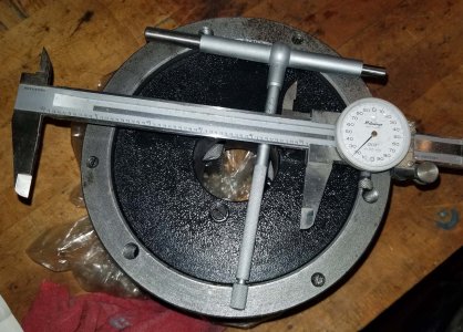
Started by measuring the diameter of the register with telescoping gauges and a caliper.
20200518_155155.jpg


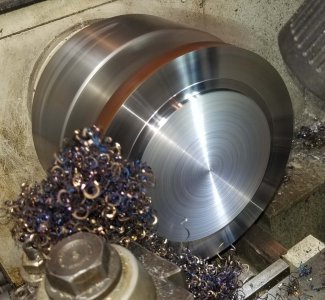
Chucked up the 8" round on my G0709 lathe. It has an 8" set-true chuck, adjusted to dial in the OD within 0.0005" and faced. Then flipped and faced the opposite side. Once both sides were faced, continued facing to leave the register for the chuck.
20200518_163840.jpg

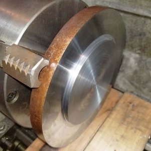
Register all finished. I faced the surface and left the register surface behind, stayed short of the diameter by around 0.030". Once I had the register at depth (0.200"), started to turn the register OD. Crept up on my number and checked with the chuck. Went a little deep on the face of the plate at the base of the register so the outside/back side of the chuck would lay on the plate, not the area at the register (register is just for radial positioning).
20200518_165804.jpg


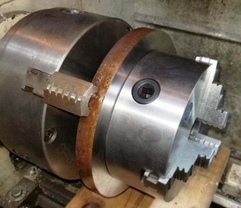
Checking the fit with the chuck.
20200518_165751.jpg


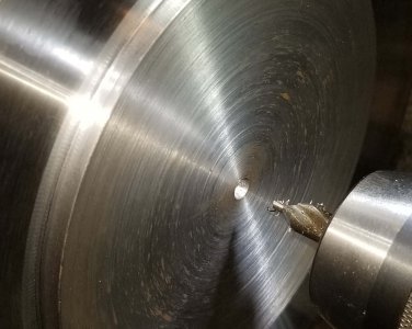
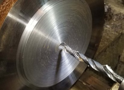
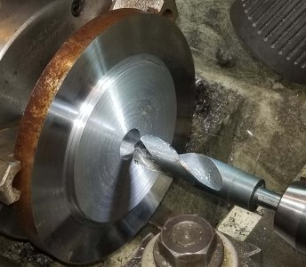
Drilled a 1" through hole in the mounting plate. Started with a center drill, then a 3/8" and a 1". This hole will be for clearance only. The 5C collet mounting arbor has a ground MT3 / 3/4" arbor for centering the 5C collet holder on the 4th axis. My plan is to use the same arbor for centering the 3-jaw. Set the arbor in the rotary table, set the 3-jaw in place over the arbor. Tighten the chuck on the arbor and fasten the chuck to the rotary table with bolts/T-nuts.
20200518_170018.jpg20200518_170152.jpg
20200518_170636.jpg


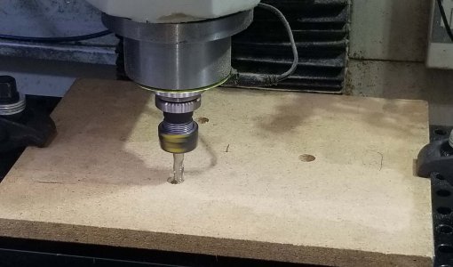
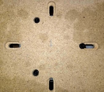
Tormach CNC equipment uses controller software called PathPilot. Tormach has an on-line version of the software which is great for writing routines and proving them out on the screen. However, I still go with a particle board prototype on occasion.

20200523_141651.jpg
20200523_152934.jpg


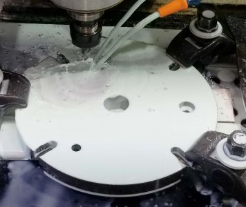
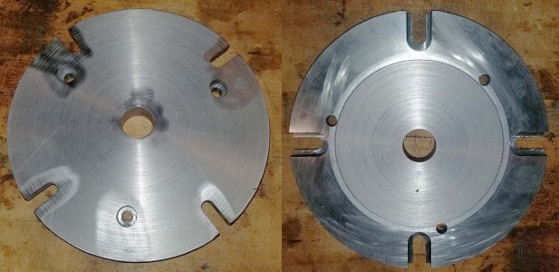
The 3-jaw chuck has three mounting holes at 120 deg. apart. The rotary table has 4 T-slots. I'm a little out-of-date on my calculus to take the differential of a formula with 3 peaks on a circle vs. 4 peaks to find the optimal rotary spacing between the two. So, ran the two routines in the particle board with one of the holes/slots lined up. The mounting plate would have countersunk pockets for the chuck and countersunk slots for the rotary table. These features are on opposite sides of the mounting plate, so the plate will have to be flipped between routines.

You can see on the RH hole/slot that they slightly overlap. I figured the best spacing would be putting one of the chuck holes evenly spaced between two of the slots. That'd put one hole at 45 deg. to the adjacent slots and the other two holes 15 deg. from their closest slot.
20200523_154024.jpg


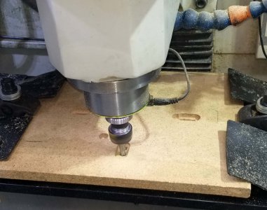
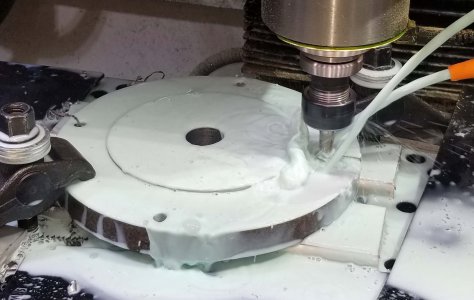
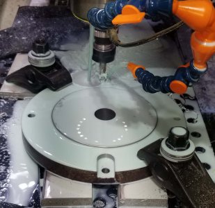
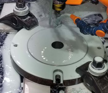
I ran the 4-slot routine first. Found center using a passive probe on the register. The CNC routine used 3 tools: spotting drill, 11/32" drill bit and a 3/8" roughing end mill.


Spot drilled, through hole drilled and milled a 3/4" wide pocket for cap screws (to screw to T-nuts on the rotary table).
20200523_161336.jpg
20200523_161828.jpg
20200523_163246.jpg

First side done.
20200523_170244.jpg


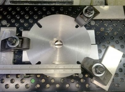
I flipped the mounting plate and scribed a line along the tangent point of two of the T-slot holes. Then stuck a couple of dowel pins in the Tormach's fixture plate, laid a scale against the dowels, and an adjustable parallel on top of the plate. Rotated the mounting plate until the scribed line lined up with the top of the parallel, then clamped the plate in place.
20200523_185022.jpg


The chuck pocket hole routine used the same three tools: spotting drill, 11/32" drill bit and a 3/8" roughing end mill
20200523_190053.jpg
20200523_190708.jpg

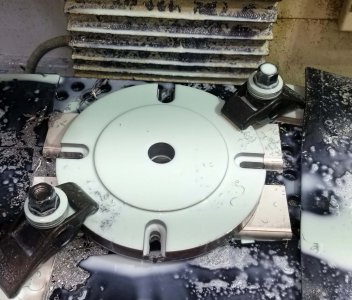
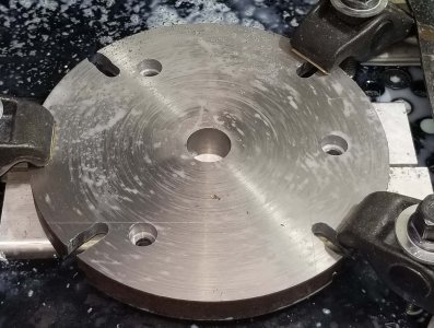
Finished backing plate. Ran the edges over a Scotch-brite wheel and stoned the back side of the chuck through holes.
20200523_192728.jpg


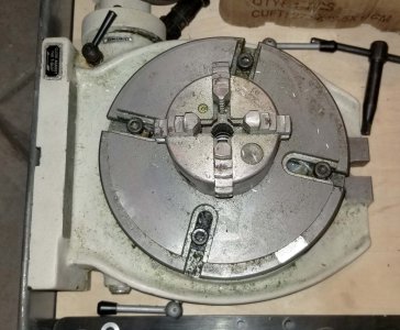
My 4th axis has the 4-jaw on it for now, but . . .
20200523_193455.jpg


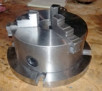
Finished mounting plate with the 3-jaw mounted.
20200523_193447.jpg


Thanks for looking,

Bruce
 
Last edited:
Well today I put up the majority of the iron pipe for the air system in my shop.
I also order a harbor freight air dryer they are currently on sale for $300.

Also waiting on a whip and air filters for my compressor from mcmaster Carr.

Hopefully tomorrow I can finish the majority of the electrical.

fe7ec3444b4d2e02e53e38f7089e89d3.jpg
 
POTD was making a backing plate for a 6" 3-jaw chuck. My Tormach mill has a 4th axis; basically a rotary table that's programmable. I have a small 4-jaw chuck and a 5C collet holder, but wanted to be able to mount a 3-jaw also. Bought a no-name 3-jaw off eBay about a year ago, plus an 8" CRS round 1" thick.


Started by measuring the diameter of the register with telescoping gauges and a caliper.
View attachment 325269


Chucked up the 8" round on my G0709 lathe. It has an 8" set-true chuck, adjusted to dial in the OD within 0.0005" and faced. Then flipped and faced the opposite side. Once both sides were faced, continued facing to leave the register for the chuck.
View attachment 325270

Register all finished. I faced the surface and left the register surface behind, stayed short of the diameter by around 0.030". Once I had the register at depth (0.200"), started to turn the register OD. Crept up on my number and checked with the chuck. Went a little deep on the face of the plate at the base of the register so the outside/back side of the chuck would lay on the plate, not the area at the register (register is just for radial positioning).
View attachment 325272


Checking the fit with the chuck.
View attachment 325271


Drilled a 1" through hole in the mounting plate. Started with a center drill, then a 3/8" and a 1". This hole will be for clearance only. The 5C collet mounting arbor has a ground MT3 / 3/4" arbor for centering the 5C collet holder on the 4th axis. My plan is to use the same arbor for centering the 3-jaw. Set the arbor in the rotary table, set the 3-jaw in place over the arbor. Tighten the chuck on the arbor and fasten the chuck to the rotary table with bolts/T-nuts.
View attachment 325273View attachment 325274
View attachment 325275


Tormach CNC equipment uses controller software called PathPilot. Tormach has an on-line version of the software which is great for writing routines and proving them out on the screen. However, I still go with a particle board prototype on occasion.

View attachment 325276
View attachment 325277


The 3-jaw chuck has three mounting holes at 120 deg. apart. The rotary table has 4 T-slots. I'm a little out-of-date on my calculus to take the differential of a formula with 3 peaks on a circle vs. 4 peaks to find the optimal rotary spacing between the two. So, ran the two routines in the particle board with one of the holes/slots lined up. The mounting plate would have countersunk pockets for the chuck and countersunk slots for the rotary table. These features are on opposite sides of the mounting plate, so the plate will have to be flipped between routines.

You can see on the RH hole/slot that they slightly overlap. I figured the best spacing would be putting one of the chuck holes evenly spaced between two of the slots. That'd put one hole at 45 deg. to the adjacent slots and the other two holes 15 deg. from their closest slot.
View attachment 325278


I ran the 4-slot routine first. Found center using a passive probe on the register. The CNC routine used 3 tools: spotting drill, 11/32" drill bit and a 3/8" roughing end mill.


Spot drilled, through hole drilled and milled a 3/4" wide pocket for cap screws (to screw to T-nuts on the rotary table).
View attachment 325279
View attachment 325280
View attachment 325281

First side done.
View attachment 325282


I flipped the mounting plate and scribed a line along the tangent point of two of the T-slot holes. Then stuck a couple of dowel pins in the Tormach's fixture plate, laid a scale against the dowels, and an adjustable parallel on top of the plate. Rotated the mounting plate until the scribed line lined up with the top of the parallel, then clamped the plate in place.
View attachment 325283


The chuck pocket hole routine used the same three tools: spotting drill, 11/32" drill bit and a 3/8" roughing end mill
View attachment 325284
View attachment 325285

Finished backing plate. Ran the edges over a Scotch-brite wheel and stoned the back side of the chuck through holes.
View attachment 325287


My 4th axis has the 4-jaw on it for now, but . . .
View attachment 325289


Finished mounting plate with the 3-jaw mounted.
View attachment 325288


Thanks for looking,

Bruce
Good deal on the chuck mount. Very handy. What CAM software do you use for your Tormach?
 
I use PathPilot. It has pretty decent conversational program routines which can be linked together.

For example, there's a pocketing routine where you spec the tool number, spindle speed, feed rates, WOC, DOC, Z clearance for moves between holes/slots, start Z, end Z, and spot drilling if you chose to. Spec the X and Y width of the pocket. The x,y for multiples are listed in a drill/tap table. For the T-slots, did a routine for a 0.75" wide by 1.5" pocket that was 0.32" deep. Saved that out, then edited it for a 0.4" by 1.00" pocket that was 0.75" deep. Loaded the first routine and linked the two together.

That being said, it's far from perfect so some G-code manual programming knowledge helps. Their generated G-code is very heavily commented, so pretty easy to modify.

The big plus is they have an on-line version so I can write the program in the den, run it virtually, debug, dump on a jump drive and load it on the controller in the shop.

Tormach is pretty good about fixing bugs too. I wrote a routine to engrave the USMC insignia using a DXF file. Something like 500 spindle ups/downs as it moved around the logo. PathPilot did a spindle off/coolant off before each move. Then restarted when at the next shape. It was pretty easy in G-edit to turn all of the offs to comment lines, but still. . . Sent Tormach a copy of my routine and comments, the net version of PathPilot fixed the problem.

Bruce
 
Got it. Ya Tormach people are helpful. I have an 1100 tormach also and agree the conversational programming in pathpilot is very handy for rectangles, circles, drilling etc. I went with Sprutcam just because some of the shapes I needed to cut wouldn’t be possible. I guess I was curious on the rotary how you program that. I could see manually programmed for indexed type work just not simultaneous 4 axis milling. That would be some gnarly hand code! Did your rotary come with a tailstock? I don’t have one yet and need to support for longer work.
 
Well, on my "list of good intentions" is learning Fusion 360. Titans of CNC has a great tutorial series.

On the other hand, my wife is a Unigraphics designer which apparently has some CAM in it. We also have a full-blown copy of SolidWorks and have a CAM package for that. However, I haven't taken the time yet to investigate further as so far haven't done anything that needed CadCam. The guy I bought my Tormach from was a big Fusion fan and did some rudimentary 4th axis work.

I do have a tail stock for my 4th axis. Also have the homing kit which I need to install. I have a couple of jobs that'll use it this summer (gear cutting). I'll manually code those which is pretty simple. I'm familiar enough with running subroutines and looping to set up a "cut a tooth" subroutine, then run the gear by rotating the 4th and call the subroutine. Will be sooo much nicer cutting a 75-tooth gear without a dividing head!

Next project won't be a big money maker for me, more of the challenge than anything. I reproduce old Erector set parts on occasion and am planning on making their old part number 'FL' helical gears. It's a 12-tooth 45 deg. helical made from brass, OD is around 1/2". My plan is to mount the 4th at a 45 on a tilting angle plate. I've got a few of the original parts, just need to measure the depth of the face and the rotational angle between the start and end of a tooth. "Should" be able to program a coordinated move like "G1 X0.5 Z0.5 A30" (for example) to move the X/Z at a 45 along the blank while the 4th rotates the blank 30 degrees.

Bruce
 
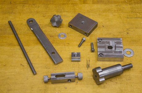
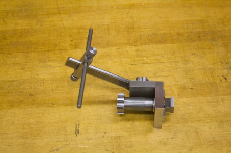
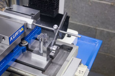
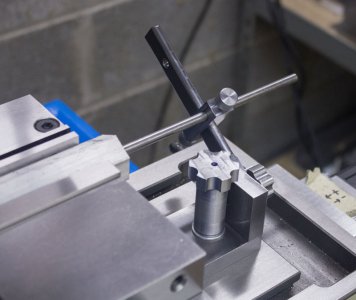
I decided to remake my mill stop completely out of steel. I had made one with most of the parts aluminum, but I found there was more flexing in the arm than I cared for. So, I remade it with 1018 steel and used FreeCAD and LinuxCNC for some of the parts. The base part has "keys" to mate with the T-slots were mostly cut by CNC, but I had to finish it manually. FreeCAD had some weird motions doing 45 degree passes and it left a lot of material.

I used CNC to cut the two large bolts patterns on the top rather than knurl them for gripping. I used a 1/8" radius 5/8" diameter corner rounding end mill to round over the 1/4" arm so it fits the slider slot perfectly without filing it square (which I did on the first one).

Disassembled:
IMG_5574.jpg
Together:
IMG_5576.jpg
In use:
IMG_5577.jpg
Another in use:
IMG_5578.jpg
 
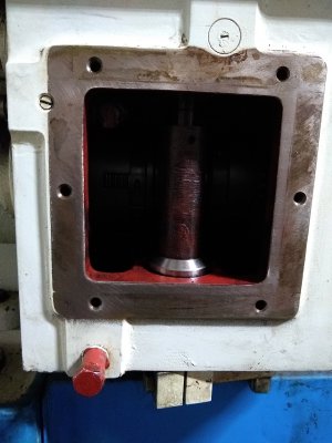
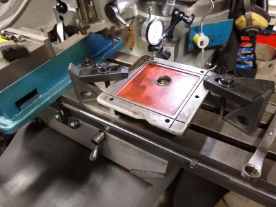
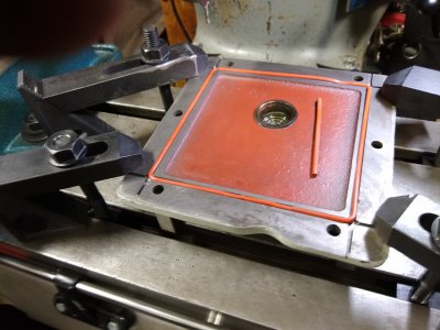
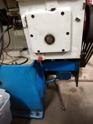
Have had a leak on my TOS lathe since I got it, and had a drip pan under it which would predictably get kicked, or moved by some random action in the shop leaving a puddle on the floor. Finally traced it down to a weeping cover plate. Drained it and removed the cast cover and found a square o-ring in a machined slot. After some measuring it seems the slot was machined a wee bit too shallow for the o-ring material to effectively do it's job. Looked through my stash, and found a round o-ring long enough, but considerably thicker and, wider than the original. Set the cover up on the mill, which was a bit of a challenge as the front of the cover is as cast. So after the judicious placement of some shim stock to get things level, I needed to get it squared up. Put a piece of 3/8 round stock in the lathe and cut a shallow angle on it, chucked it up in a collet on the mill,placed it in the existing o-ring groove and used the X axis of the table to square things up. I could have used an indicator to do it, but this idea popped into my head, and decided to humor myself. Machined the existing o-ring groves wider, and deeper, reinstalled the cover with a dab of silicone at the mating ends of the o-ring, and after 4 days, no leak. Another small, but satisfying job ticked off the list. Cheers, Mike


IMG_20200502_212516816.jpgIMG_20200501_190519031.jpgIMG_20200502_181959162.jpgIMG_20200525_102036705.jpg
 
Back
Top