Adventures in my new-to-me Enco Lathe

OK, I got out to storage today and made the measurements. These are for my motor and my G9249 which I purchased in 2000.

As you can see the layout is very different, my numbers are shown in red.
View attachment 332866
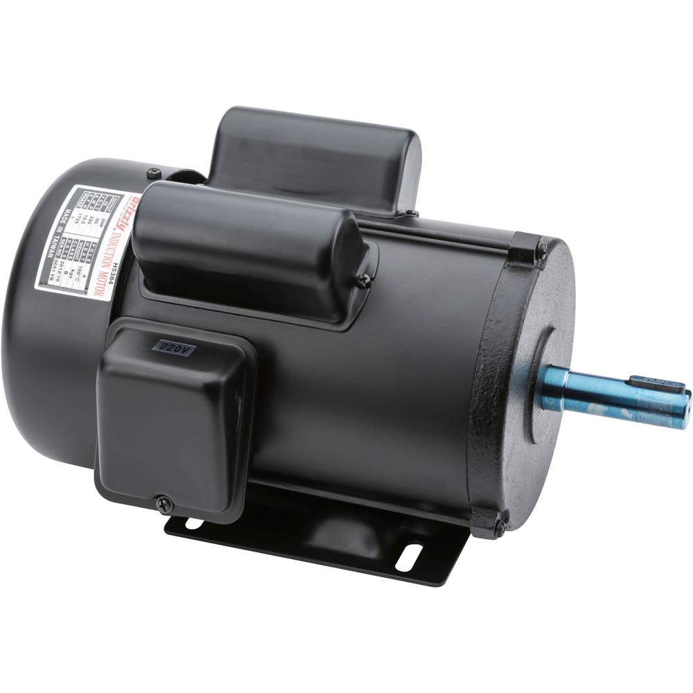
Here is an image of the plate on my motor

Thanks, super helpful. I think I'm going to hold off on more G9249 parts and see about maybe jet parts at replacements. The JET BD-1336T seems to be a pretty close make, but that's been tough to verify has replacements.

There's the BDB1340 which looks to be a modernized equivalent and that uses a BDB1340-MP pulley that may work. According to the info it has a 19mm ID which makes sense from what I'm seeing. I'm going to order one and hopefully this toolpartspro website doesn't take as long as the reviews indicate. Then when I get it figure out what motor fits best.
 
Glad that it helps. Always fun trying to figure this stuff out.

If you really want a new motor, I would go to Grainger and see what they can match up for you. Motors conform to NEMA standards, meaning that a specific NEMA Frame number, regardless of who the motor comes from will bolt into the same NEMA Frame number.

What I find interesting is that the diagram on my lathe for speed adjustment shows the larger pulley on the motor is on the outside. But as you can see in the picture above the larger pulley is on the inside. My speeds work well but changing from the A to the B configuration is a pain in the backside. So much so, I think I have actually done it once. To make it worse, there is a cover over the motor pulleys that you have to remove to make the switch.

Spindle Speed Chart.JPG
 
If you really want a new motor, I would go to Grainger and see what they can match up for you. Motors conform to NEMA standards, meaning that a specific NEMA Frame number, regardless of who the motor comes from will bolt into the same NEMA Frame number.
After doing the conversion do we think it's likely that the pulley is 22mm? It's basically 7/8" but the only motors I was seeing on grizzly's list that uses 7/8" were 3HP, but I realize now it could have been this 22mm shaft.
1596988763665.png
I guess the way to tell is if the Key is 7mm or 5mm.

I keep going back and forth on what the best thing to do is. I was tempted by the JET replacement but it's about $100 more expensive than the grizzly, and having given it some more thought I feel pretty comfortable with the grizzly originals.

That is weird on the lathe pulleys. I didn't find it too challenging to change speeds, but perhaps because my pulleys were inverted the step change wasn't much
 
Ok wow this pulley looks absolutely nothing like yours. Maybe it's the wrong part? I used the word adventures tongue in cheek at the start, but man this is an adventure in annoyances.

1597427341859.png
 
Since your lathe has a three step pulley, seems extremely likely that the motor pulley should be also. Step pulleys are almost always installed so the belt runs from the larger diameter to the smaller diameter in reverse order. That way the CC distance remains fairly constant. "normal" orientation of the pulley steps on the motor are to have the smallest away from the body of the motor. Makes changing speeds a little easier. When you position the motor try to get the belts to run parallel to the grooves in the pulley so it doesn't rub more on one side than the other. The photo showing two grooves the same size is likely used for a two belt drive, common on larger horse power applications. Especially when small diameter pulleys are being used.
 
The motor side only have two pulley grooves for speeds.

I agree with you on the pulley alignment. Makes sense to me that you'd want to keep you CC consistent but for some reason that's now how the math works to get the speeds they specify, unless their top end speeds are not accurate:

Reminder of what the speeds should be:
AC 1250
AD 950
AE 730
BC 530
BD 400
BE 310

and here's what they'd calculate out to. The gap between AE and BC is too small, AC doesn't get high enough and BE is faster
1597505576280.png


These numbers make more sense when you add in a bit of drag, they'd work out almost perfectly to the specified values. But the step change is all wrong for easy swapping between the motor pulleys
1597505708032.png
 
The photo showing two grooves the same size is likely used for a two belt drive, common on larger horse power applications. Especially when small diameter pulleys are being used.

Yeah it's just supposed to look like what Papa Charlie posted with the two steps

Here is an image of my motor pulleys.
View attachment 332867


And what the grizzly manual shows for the part:
1597506094270.png


I'm hoping it was a mistake on grizzly's part but maybe I'm just destined to not be able to find replacement parts for this chunk of steel
 
mkelly - I feel your pain, I am going through trying to figure out the same motor pulley issue as you. My used G9249 came with a replacement Baldor motor that only has a single 3.625" pulley on the motor drive shaft, and I'm trying to get back to a step pulley setup.

The pulley you got from Grizzly is the same pulley they just sent me this week for my G9249. It is obviously the wrong pulley; Papa Charlie's picture clarifies that. I have an email into Grizzly's tech support, we'll see what they say, but I'm pretty sure someone in the labeling/packaging department was not on their game.

The picture of your speed chart in post #12 depicts the pulley on your motor drive shaft how it came installed on your lathe was correct, but the chart depicts the idler pulley for the motor drive belt flipped around from how it is installed in your lathe from your picture in post #8.

The Grizzly speed chart depicts the idler pulley for the motor belt as it comes installed in the lathe, but the speed chart depicts the pulley on the motor drive shaft flipped around from Papa Charlie's picture and how it is pictured in the parts diagram. It's like the guy drawing the speed charts and the guy installing the pulleys had no communication with each other. So which one wasn't doing their job correctly?

To make matters worse, look at the picture on page 35 of the Grizzly G9249 manual. It is captioned "Motor V-Belt in "B" position". Now look at the spindle speed configuration chart on page 34. It sure looks like the motor v-belt in the picture on page 35 is in the "A" position according to the chart on page 34. So is the caption for the picture on page 35 correct or is the speed chart correct?

We'll see what Grizzly says, but right now I'm leaning towards just getting a cheap tachometer and a set of 2" and 4" pulleys for the motor shaft and seeing what configuration gets me close to the speed chart...that is if the speed chart is even correct???

Please let us know if you come up with a solution on your end. Thanks - Owen
 
I think they may have sent you the wrong pulley. The purpose of having the two sizes of pulleys is to allow for movement from one pulley set to the other and maintain the belt tension.
 
It might be easier to just figure out the ratios for yourself. Gears are easiest because it is just the tooth count. V belt pulleys need to be figured using the pitch diameter rather than the outside diameter. But you can come close enough by just using about 3/8" of an inch less than the OD or the pulley. Or you can look the pitch diameters up on a site that sells belts & sheaves to industrial customers.

It would be pretty easy to set up a spread sheet and work your way backward from the speed chart.
 
Back
Top