An Electronic Lead Screw controller using a Teensy 4.1

Most modern processors use 3.3V and under. A lot of the modern semiconductor nodes operate at 1.8V or even 0.9V. The more advanced nodes use low voltages to reduce heat and to avoid electrical breakdown due extremely small transistor features. No one has figured out how to change the voltage breakdown of silicon. It breaks down at a certain field strength. If you make the transistor smaller by 1/10, the local field strengths increase by 10. Hence, the reduction in Vcc as the transistor sizes have been shrinking. So level translation is just what you have to do.

I chose the Teensy because it was fast, had lots of memory, and had quadrature encoders. But I have never used it before. Hope not to have to read all of the hardware docs, but I'm sure that I'll have to read a few of the sections quite thoroughly.

Kind of intrigued by @greenail's implementation of an ELS with his DRO. I have a DRO on my lathe, although it only displays to 0.001" increments. Would be nice to be able to get to the shoulder and stop without losing thread synchronization. Think it's possible. Just daydreaming...
 
Nothing wrong with 3.3V unless you need to interface with 5V circuits (encoders). Sometimes it is just nice to have the processor at the same voltage level
 
The encoder, step and direction signals are generally 5V, but it's not many signals and having some kind of driver/receiver is advisable anyway in a noisy machine environment (rather than connecting fragile micro pins directly to cabling).
 
But thanks for reminding me about level translation. I will have to find some parts to do that. The 74LVC245 is a bus driver that is 5V tolerant. Could use one powered at 3.3V to read the encoders. A second one powered by 5V to drive the stepper driver board. The 74LVC245 even if powered by 5V has a VIH = 2.4V, so the Teensy can drive it. The 74LVC245 is an old fashioned DIP with 8 output. Retail is $3 for 2 of them. It will cost me more in postage than for the parts.
 
For a Teensy 4.1 encoder interface I'm building for a smart industrial encoder right now, I'm using a AM26C32I RS422 Differential Line Receiver to get the RS422 differential signals buffered and converted to a 5V single ended signal. I'm then using a TXB0104 to level shift the 5V to 3.3V. (https://www.adafruit.com/product/1875). My encoder has some fast serial signals (2MHz) in addition to the quadrature, and I found that a simple FET based level shifter (https://media.digikey.com/pdf/Data Sheets/Adafruit PDFs/757_Web.pdf) had very poor distortion at these signal speeds.

If you want to drive the output at 5V single ended, a basic non-inverting buffer would do fine. I needed RS422 outputs so I went with an AM26C31 Line driver.
 
If I get a new phone, I don't want to learn how to get the display app to work again to use my lathe
It is just a web page so any browser would work, it is not an "app"

The display running over SPI is too slow to update in real time
You don't need to update the display more than 5 hz in practice. Also, with a single core you wouldn't want to try to do that in addition to monitor the encoder and generate steps.

The tough stuff is:

1. implementing acceleration
2. user interface in hardware that you like and can change and is easy to iterate on when it is on your machine.

I was recently playing around with a single axis stepper for power feeding a mill and I was thinking of also using the same code to run my rotary table. Hardware UI's suck for configuration. I really hate them and you have to sink a ton of time into them. Display code for these MCUs also sucks. Best bet seems to be a really simple hardware UI for operation and doing all the configuration via wifi or bluetooth and a simple web UI using websockets for the display/config. It is worth the learning curve.

Encoder noise is an issue depending on how noisy your spindle motor is. Differential encoders seem like the best choice.

The esp32 has a couple really nice features for this application. 2 cores allows one core to focus on the encoder and motion planning calculations. the 2nd can be used for all the other stuff. It also has a RMT peripheral which does step generation up to 200khz with no additional CPU load. Finally, the wifi allows you to wirelessly flash it and to use a web ui to configure/debug it.

I'd love to figure out a decent way to implement acceleration curves. The issue is that with the spindle running you have a period where an acceleration ramp is needed to get to the right position. This will always be in error until the stepper gets up to speed and is also in sync with the spindle encoder position. The issue is making the out of sync startup time as small as possible. In my setup a close loop stepper seems to be best as it can compensate for the acceleration issues when threading. Plan B is just to tell the thing to jog with the spindle off and when you turn the spindle on it maps it's acceleration to the spindle's acceleration and should be perfectly in sync.

With respect to the naïve implementation, the simple way to do it is.

1. set sync point from encoder.
2. when "engaged" calculate the correct position (using Bresenham line interpolation calculation is good start)
3. if correct_position > current_position then step the right direction.
4. if correct_position < current_position then step the left direction.
5. else do nothing

This slaves the X motor to the spindle and will work at any speed (assuming your encoder can keep up). It also works with the machine stopped.

I'm happy to help you out so feel free to ask me questions here or on github.
 
It is just a web page so any browser would work, it is not an "app"


You don't need to update the display more than 5 hz in practice. Also, with a single core you wouldn't want to try to do that in addition to monitor the encoder and generate steps.

The tough stuff is:

1. implementing acceleration
2. user interface in hardware that you like and can change and is easy to iterate on when it is on your machine.

I was recently playing around with a single axis stepper for power feeding a mill and I was thinking of also using the same code to run my rotary table. Hardware UI's suck for configuration. I really hate them and you have to sink a ton of time into them. Display code for these MCUs also sucks. Best bet seems to be a really simple hardware UI for operation and doing all the configuration via wifi or bluetooth and a simple web UI using websockets for the display/config. It is worth the learning curve.

Encoder noise is an issue depending on how noisy your spindle motor is. Differential encoders seem like the best choice.

The esp32 has a couple really nice features for this application. 2 cores allows one core to focus on the encoder and motion planning calculations. the 2nd can be used for all the other stuff. It also has a RMT peripheral which does step generation up to 200khz with no additional CPU load. Finally, the wifi allows you to wirelessly flash it and to use a web ui to configure/debug it.

I'd love to figure out a decent way to implement acceleration curves. The issue is that with the spindle running you have a period where an acceleration ramp is needed to get to the right position. This will always be in error until the stepper gets up to speed and is also in sync with the spindle encoder position. The issue is making the out of sync startup time as small as possible. In my setup a close loop stepper seems to be best as it can compensate for the acceleration issues when threading. Plan B is just to tell the thing to jog with the spindle off and when you turn the spindle on it maps it's acceleration to the spindle's acceleration and should be perfectly in sync.

With respect to the naïve implementation, the simple way to do it is.

1. set sync point from encoder.
2. when "engaged" calculate the correct position (using Bresenham line interpolation calculation is good start)
3. if correct_position > current_position then step the right direction.
4. if correct_position < current_position then step the left direction.
5. else do nothing

This slaves the X motor to the spindle and will work at any speed (assuming your encoder can keep up). It also works with the machine stopped.

I'm happy to help you out so feel free to ask me questions here or on github.
Thanks for chiming in. Especially for clearing up my mistaken notion of an app. In the distant past I played around with python-flask to make an interactive web page. It wasn't that bad to implement. I do have to agree the UI is a royal pain, especially if it morphs over time.

I wrote a program to compute and display ambiguity waveforms for radar, and I found the human interface took up a LOT of effort. A lot more effort than learning how to compute 32 million point double precision floating point fast fourier transforms using massive parallel processing. As a tidbit, moving the data to the compute engine took 10 times as long as computing it. (Network bound on a private bonded 2Gb Ethernet.) Learned a lot about super computing bottlenecks on that job.

As you learn more about what is important for the user, the displays and interaction tend to get more complicated. Sometimes so complicated, that basically one has to rip up what was done, simply because it was not flexible enough. If possible, it's far better to design a fuller interface, than to organically grow it. Organically grown code usually is a nightmare, primarily since it wasn't fully thought out. Unfortunately, I don't know much about motor control, nor the application, so I expect to flounder some on the man-machine interface.

For my radar display, the display was about 6 Hz, give or take. It was about as fast as the cheapo display could manage. The radar ran at 50Hz and detections plus that detected data frame were displayed. For my application, it wasn't quite acceptable, since I wanted to track the flight of the projectile, which should ordinarily consist of multiple detections. But hey, it wasn't bad considering it was running on a low budget M4 processor, and a $3 doppler door sensor front end. Kind of pushed it to the limit and found the limits!

For your implementation, it appears you are reading your DROs on your lathe? Are you directly reading the scales and decoding the position? I can't quite tell what your implementation is. Is there any documentation of what you have done so far? No videos, but some diagrams, or basic written description. I did view one video, which was interesting, but it left me with questions of what all the elements of your system are. Perhaps it was covered in a previous video.

And thanks for your offer of help. Good to know there's someone to ask a question or two.
 
For a Teensy 4.1 encoder interface I'm building for a smart industrial encoder right now, I'm using a AM26C32I RS422 Differential Line Receiver to get the RS422 differential signals buffered and converted to a 5V single ended signal. I'm then using a TXB0104 to level shift the 5V to 3.3V. (https://www.adafruit.com/product/1875). My encoder has some fast serial signals (2MHz) in addition to the quadrature, and I found that a simple FET based level shifter (https://media.digikey.com/pdf/Data Sheets/Adafruit PDFs/757_Web.pdf) had very poor distortion at these signal speeds.

If you want to drive the output at 5V single ended, a basic non-inverting buffer would do fine. I needed RS422 outputs so I went with an AM26C31 Line driver.
Differential is the way to go for high speed long runs. I was looking at the TXB0104. At the moment, I think the interfaces I have are all single ended, which is limiting, especially in an electrically noisy environment. My lathe is powered by a VFD, so I may run into issues. Fallback is going differential. Pretty sure the bus driver chips can handle 80 MHz toggle rates sourcing and sinking 24mA. At these speeds, the cables become transmission lines. I don't expect to run anywhere near that rate! The 24mA means that I can directly drive any opto-couplers.

At 3600 RPM (max lathe speed) that is 60 rev/second. For a 1K encoder, that is 60K codes/sec and 240K edges/second. Roughly 4us. I don't think I have ever gotten my lathe to spin that fast, I'd be afraid of some disaster! At half that speed, there would be 120K edges/sec. Running the Teensy at 600MHz, means the processor can execute 5000 instructions in that 8.33us. Once every 4.295e9 counts (32 bit roll over) we need to service the roll over interrupt. At 3600 RPM that is once every 19.88 hours. Of course this can occur much sooner, if we reverse, but trying to get an idea of the time scale. This interrupt needs to be correctly serviced because we don't ever want the machine logic to ever hiccup.

Clough42 mentioned something on his repo, that I don't think was right. Essentially he warned about the Teensy quad decoder rolling over more often. I just looked this up and the T4.1 register length is 32 bits, the same as the TI chip. Don't know if that was FUD or he was going by some old information. I'm not taking anything away from him, he was clever to pull this off using a cheap launchpad. Think the form factor of the Teensy is a bit better.
 
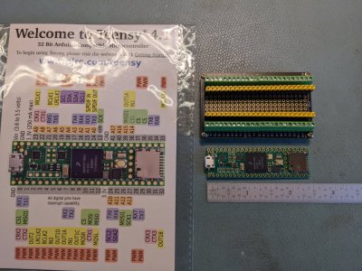
My first Teensy arrived today. Guess it is time to update my Arduino IDE and load Teensyduino!
PXL_20220504_180416634.jpg
 
For your implementation, it appears you are reading your DROs on your lathe?
it only reads the spindle encoder. Fridge DRO was a completely separate project.


I don't have much documented, the contoller it isn't that much different than I explained. The websockets and react are a bit more complicated but there are plenty of tutorials available on both. I used react hooks, but you could use just about whatever you liked. The big simplifier is the arduinojson library which serialized/deserializes the data over the websockets. You can use plain old json or move to binary optimized when you have it working.
 
Back
Top