Another Treadmill Motor Speed Controller conversion thread

Where do you see that statement? I looked 3 times and can't spot it.
Thanks
Aaron

It's in the Aliexpress link, scroll down and you'll see it. There's quite a bit of info in that ad. And I have to correct what I had written in the post above about it having no adj. pots, I now see them in the pics and written in the description. It's saying for use above 110v AC to add your own 220v-120v transformer but probably makes sense & easier just to use 220v plugged into you wall and be done with it?

https://www.aliexpress.com/item/329...earchweb0_0,searchweb201602_,searchweb201603_

50249921682_b9c0a51ac5_c.jpg
 
Last edited:
If you watch Ebay, the KB controllers come up for sale in the 50$ range. KBIC-125 is one I use, good for 16 amp, probably a bit more with forced air.
I got one for around 15$ because it was dusty, in a different box and the seller didn't know if it worked. Blew off the dust and it fired right up. Yes, the motor will hum a bit, but they are very reliable and easy to repair- no exotic parts
-Mark

Hi Mark,

I just saw your post and have to say thank you. You're correct and have been looking at those but I'm afraid on how good they are for the size motors we want to use, yes they say 16 amp when you add a heat sink to it, otherwise it's half that (8amp DC)? I guess you need to add a heat sink or buy one with it already. I also notice that I don't see any good size caps on those boards and wondering if thats an issue as well?

Are these PWM controllers? I've been keeping an eye on KB Electronics KBMG-212D's but then again you have to complete it and it's more expensive than a 125.

Looks like treadmill motors are only cost effective over a VFD/3ph motor set-up if you find a free treadmill, have parts already laying around to complete it and wire the DC controller up yourself.
By my calculations of cost for a treadmill setup after needing all the small bits and bobs in order to compete setup can easily equal the price of a new 1hp rated VFD (a cheap one). Not to mention time/labor to complete it.
Having to buy the odd pulley size, most likely a fan to cool it, the DC speed controller, heat sink, controls, enclosure, then fabricate a mount for the odd motor size; it all starts to add up really quick and not to mention your time on top of that; then factor in what RJSakowski said and shown in graph above about the loss of torque unless you're able to provide a gear ratio to provide the rpm's that works reasonably well for your machine. Using a treadmill motor for a drill press seems to defeat the purpose of mostly why you do it as you want more range in speeds (look at RJSakowski's graph), almost always the purpose is to slow it way down the rpm's with torque to work with hard steel unless if you have a sensitive drill press or looking for higher speeds to drill tiny holes on your regular drill press or willing to accept higher speeds to avoid changing belts? This setup would also not work on my Emco Compact 8 lathe but would probably be fine on other older lathes or mill with a pulley system that can be altered but then again it needs to be geared way down to match the speeds of a 1725 motor and still have torque.

When you add up all those things, it makes it a less viable & economical option over a VFD set up? You can buy a spanky new VFD in it's own enclosure with controls now a days for around $75 (asian) that will work on a used 1hp 3ph motor (that can be found for cheap, same or lower as a treadmill motor), thats pretty much a plug and play (low labor) setup and doesn't need all the bits and bobs to work. Just needs some wire and programming and you're good to go. I'm now having a very hard time trying to justify all the work to accommodate a treadmill motor setup over a VFD/3ph motor setup for most scenario's in a shop.

If you already had all the things laying around or found them on pennies on the dollar to make a treadmill motor setup, then it does makes a lot more sense. Especially if you are an electronics whiz like RJSakowski.

Sorry if I'm sounding pessimistic or negative on this subject, I was hoping this was not the case and please correct me if I'm wrong (I hope I am wrong) and I'm still very interested in learning more about DC motor setups and listening to others on what they think about a treadmill setup, and learning how you guys are solving this and done inexpensively. Cheers
 
Last edited:
Here's the video that was supposed to be linked above.

Using 555 times as PWM controller

The reason I was leaning towards a treadmill motor is because the motor is capable of hauling my butt across a belt that's gliding over a piece of glorified plywood, even at small speeds.
They seem pretty high on torque at low speeds.

I don't understand how people pull up these graphs and such but it will be fun to try, even if it doesn't work.

I am using this PWM controller on a MC-2100, it works but seems to be a bit finicky at times. I probably just haven’t found the sweet spot of the trim pot. It’s on a 2x72 belt grinder.
 
I have been using a treadmill motor on my Taig lathe now for several years. I set it up with the MC-60 treadmill motor controller. I also installed the big transformer looking choke coil and that really smoothed things out. I have had no problems running the setup with NO fan. I did find lots of information that helped me in doing the wiring. I set it up so that I can stop and start it back to the same speed. I included a DPDT switch to run the motor in reverse if desired. Just for grins I put in a "JOG" button as well. Lots of information on these online.
It runs great and the 2.65hp motor has plenty of power.
 
Here's the video that was supposed to be linked above.

Using 555 times as PWM controller

The reason I was leaning towards a treadmill motor is because the motor is capable of hauling my butt across a belt that's gliding over a piece of glorified plywood, even at small speeds.
They seem pretty high on torque at low speeds.

I don't understand how people pull up these graphs and such but it will be fun to try, even if it doesn't work.
Thanks for posting the link. His circuit is very similar to the one I am building.
 
It's in the Aliexpress link, scroll down and you'll see it. There's quite a bit of info in that ad. And I have to correct what I had written in the post above about it having no adj. pots, I now see them in the pics and written in the description. It's saying for use above 110v AC to add your own 220v-120v transformer but probably makes sense & easier just to use 220v plugged into you wall and be done with it?

https://www.aliexpress.com/item/329...earchweb0_0,searchweb201602_,searchweb201603_

50249921682_b9c0a51ac5_c.jpg
That is what I was afraid of. There has to be some wiggle room as most mains have some variability over5 time but they make it fairly clear that even 115 v can damage 5the driver.

There is a work around and that is to use a low voltage transformer of sufficient current capacity as a bucking transformer. For instance, a 12 volt transformer set to for bucking will drop 120 volts down to 108 volts. The trick, of course, is to find a 12 volt 15 -20 amp transformer. Buying new will cost an arm and a leg. Even on eBay, sellers seem to think that there they have gold rather than copper windings. One source my be an old battery charger. Another possibility would be winding your own. using a Variac core for a starting point. 21 turns of 14 AWG wire on my Variac core would yield a 12v. 20 amp transformer. This is beginning to get very complicated though.
 
Yesterday I ordered three PWM controls from Banggood. They are the same ones that I linked to in post #26. They should essentially function the same as the circuit in post #43. I am working on the design for the power end now and the result should work with both my original circuit and the Banggood circuit.
 
Yesterday I ordered three PWM controls from Banggood. They are the same ones that I linked to in post #26. They should essentially function the same as the circuit in post #43. I am working on the design for the power end now and the result should work with both my original circuit and the Banggood circuit.
It looks like it has the same component structure as the schematic. Maybe I should just pick up one or two of those.

I'm going to have to see how much torque I get from the PWM at 115V. I don't need a 4000rpm drive on my mill or lathe so I could probably go pretty small on the primary pulley. Will I need more than 1000rpm? If not I could improve the torque fourfold by using a 4:1 reduction in my sprockets.

With an Arduino I could have presets. Maybe this Winter I will work on an Arduino PWM controller. With an UNO I could have 10 presets plus an analog input for a wiper rheostat.
 
So, digging deeper.

Since I don't need a treadmill, I decided to take apart the console to see what was going on in there.
The treadmill is a Nordictrack T6.5S. It has a lot of bells and whistles on the control panel. It has presets and iPod input and even a crazy interface that allows you to pick different spots all over the world to simulate the terrain.
AKA, a ton of needless BS.

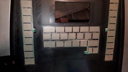
On the left side of the console is 10 different incline presets. And a manual up/down button. Don't need that.
On the bottom is a bunch of different presets for workouts. Don't need those
On the right side is 10 presets for speed. HMMM.... There's also a speed up and speed down setting.
Then there's a volume up/down function and a start/stop button.

nordictrack-t6-5-treadmill-ntl17915-7-3[1].jpg

The "buttons" are just membrane buttons. All in all, there's a main trace (fancy word for electrical connection) and then a handful of returns. These can be turned into momentary buttons.
Resized_20200821_224634.jpeg.jpg

In essence, it's possible to use the 5"X8" circuit board as the motor controller. Why do I want to do this? Assuming that the tackometer built into the belt is actually returning input to the driver to maintain speed vs load, then this would be able to maintain spindle speed under load.

Why would I NOT want to use this? It's a frikkin treadmill screen. It won't tell me RPMs or anything like that. It will also, presumably, only keep track of speed as predefined AS a treadmill.
Now, it wouldn't be too difficult to figure out how to add the tack to a spindle but it would never read RPM. It would read MPH. I'd need to add a chart to translate RPM to Spindle speed.

That's all UNLESS, I just abandoned the readout on the console and, instead, just put a tach on the motor (or spindle) and used an exterior display for that.
Given that option I'd just need to figure out the startup routine on the controller board and then either simulate that, or add buttons to make it work like this

1) Push start button
2) Select Speed preset or increase speed manually
3) Press stop button

It would be easy enough, I guess, to have a rocker for the start and stop, like normal.
Then 12 buttons, total, for speed. Or a rocker for increase speed, and a rocker for decrease speed, and a 10-stop dial switch for the 10 different presets.

All, just to allow the tach to maintain speed under load.

Decisions, decisions.
 
Last edited:
Back
Top