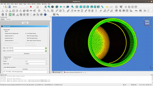
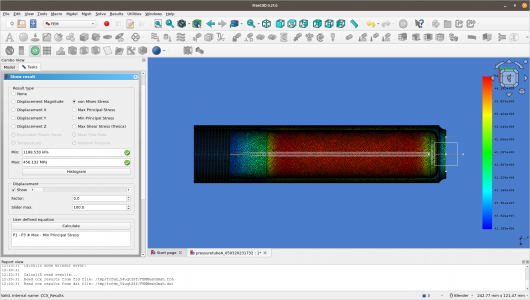
Anyone know how to use the FEM analysis tools in FreeCAD?

WobblyHand

H-M Supporter - Diamond Member
H-M Lifetime Diamond Member
Joined
Dec 18, 2019
Messages
6,448
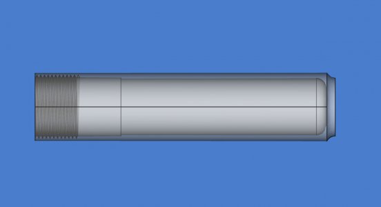
It seems the docs haven't quite caught up with the software. Trying to see what happens if one internally pressurizes an aluminum cylinder acting as a pressure vessel. It's a toy exercise for me, but the one example of FEM I found is using a different version of the tools. Having difficulties applying the constraints, and getting a mesh to work. I know the design is not best practice for a pressure vessel - I want to see where the stresses are.

There's an o-ring seal on the smooth inner ID, that prevents the threads from being pressurized. I've been told, and have seen other simulations that show sharp inside corners are very bad. I'd like to see those stresses show up in my FEA. Any tips or pointers would be appreciated.
 

Attachments

  • pressuretube.FCStd
    751.6 KB · Views: 2
I know in the older version (.19?) you needed to download the FEM version. Took some effort to get anything useful, didn’t get past a few basic shapes.
 
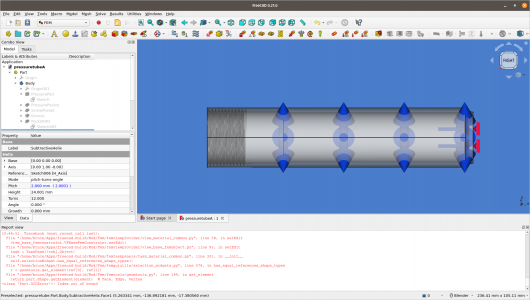
I've found some simple videos which show the basic idea, but nothing for pressurized containers. Having some difficulty selecting the internal faces, and meshing hasn't succeeded. I can get the force outward on the cylindrical wall, but not on the end. Perhaps I have to add that in a separate instance.

I built the code, and FEM was part of it. Did have to install gmsh, ccrx, and a few other tools separately, but still no joy.

Think I will attempt an easier example first, just to get through all the steps. Mind you, I have never done FEM ever, so there's a learning curve... Saw someone doing FEM in Fusion and wondered if I could do that in FreeCAD. There definitely have been times when doing some sort of FEM would have been helpful.
 
I simplified the model a bit. Finally got the pressure outwards inside the tube. When I tried to open the MaterialSolid I got a traceback, which is usually not a good sign. Yesterday I thought I had edited a material card for 7075, but perhaps I saved it in the wrong place. Yes, I saved it where FreeCAD suggested... The traceback is complaining about the model, but Part Design sees no issues. Don't know where the issue lies just yet. Posted in the FreeCAD FEM Forum - hoping for some sort of clarity. In all of the FEM examples, I have found nothing similar. For all I know, I found a case that FreeCAD cannot do!
1682867046794.png
Kind of fun doing this. Learning something new.
 
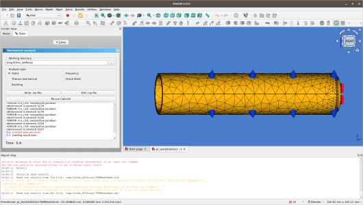
Took out the threads to simplify the model. Finally got it to mesh although there were two warnings. When FreeCAD created the mesh object it put it in the wrong place... Why that is, I do not know... Put it in the correct place in the heirarchy, and meshing was able to complete. Unfortunately, the analyzer has quit due to a non positive jacobian fault. Still, it is some progress...
pt_prelim_mesh_ccxfail.png
Have to say, this is quirky as all get out - a work in progress.
 
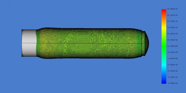
After failing big time, multiple times, with a little help was able at least to simulate someone else's file. Fortunately their file is quite similar to mine. I have much better meshing now. At least for this model, there's a peak von Mises Stress of 412 MPa in the cylinder. Since the material is aluminum, one has to pay attention. I have much to learn about FEA.
thomas_pt.jpg
I made a maximum mesh size of 1.5mm, (roughly 1% of the length) rather than letting FreeCAD auto-mesh. Previously I had let the mesher choose the appropriate size mesh. It seems it isn't quite smart enough to choose wisely.
 
This software is quirky. The model above meshed fine. A slightly different one didn't. The mesher seems to be quite sensitive to minuscule (and unintentional) details in the model. The mesher gmsh that I have is quite old. I will check to see if a more modern version is a little better behaved.
 
A newer version of gmsh is the ticket. It doesn't die when the model is slightly more sophisticated. If you are doing FEM on FreeCAD, make sure you have the latest version of gmsh.
simplified_pt_with_5mm_fillet.jpg
pt_3p5x_workingPressure_7075T6_5mmfillet_1p2mm.png
Stress is now spread out a bit on the 5mm radius of the fillet. Newer gmsh seems to allow finer meshing. One caution, FEA uses a lot of memory. At a 1mm max cell size, memory usage peaked at 28GB. My computer has 32GB, so getting close to the edge. At least with the default settings, the Solver will use 100% of your CPU's for an extended period of time, like a couple of minutes. Make sure your fan and heat exchangers aren't full of dust! The stress value calculated at 1.5mm cell size was within 0.5% of the 1mm cell, so in most cases, it's not worth the additional computational load.
 
I redid the mesh to 0.99 mm, which is pushing the limits on my laptop. (Used 90% of my RAM at peak load. This is about a 6 minute simulation.)

I tested three pressures in the tube. 105 MPa, 90 MPa, and 75 MPa. These are 3.5, 3.0 & 2.5 times the working pressure of 30 MPa (4351 PSI). Only the 2.5x shows maximum von Mises stress (456 MPa) below both the tensile yield strength (502MPa) and the ultimate tensile strength (572MPa). I think this means, that this design has a rough 2.5x safety factor. Is this interpretation sensible?
1683391897770.png
 
More woes. The mesher seems to have a mind of its own... Or FreeCAD is picky about how it sends the model to the mesher. Or who knows what. Been pretty frustrating. Created a new model which just isn't that different than above, and it won't mesh it. Being new to both FEA and FreeCAD, makes this less fun than it ought to be. There are definitely quirks to this. The errors returned are not helpful to the user, especially to me.

Found something useful. For some reason, the mesher has a poor default setting. It's labeled as experimental, and it is checked, but the option to uncheck it is greyed out! Err, not friendly at all. Eventually, searching for an hour I found a way to uncheck the box. Once I did that, the mesh ran and completed with no errors. How weird is that. Have to do the following:
Tools> Edit Parameters > BaseApp > Preferences > Mod > Fem > General, then change AnalysisGroupMeshing from true to false.
It's nice to know this, but believe me, I never would have found this arcane bit on my own. The issue was raised in 2020, but has yet to be fixed.

Of course, just getting a mesh isn't enough. The solver has to be able to solve it. Using the default solver seems to invoke all the cores to 100% and uses 100% of my RAM and 100% of my allocated swap. It does eventually finish, but there seems to be a bug, and the results are not written to file! So it takes a long time and there's no results. Kind of frustrating. If I use the iterative solver, it seems to only use one core, and 8GB of RAM. If it runs to completion, it may take, not sure, about 4 hours. Don't know if it will be successful. At least it isn't making my PC fans scream. I think it is time to section the model to take advantage of symmetry. Maybe I will cut it into quarters and simulate just one of them. Used pseudo-threads in the model, so it really is symmetric no matter which angle (in cylindrical coordinates). The pseudo threads are not in the high pressure region, so there's nothing interesting going on there.
 
Back
Top