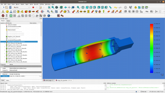
Anyone know how to use the FEM analysis tools in FreeCAD?

Well got a lot of this sorted out, at least the meshing and stuff like that. Now the sims take under a minute. Made a quarter model and fixed the weird meshing, by un-selecting the experimental crap. This tube was made of 2024 either T3 or T5.

Anyways, with a 0.5mm inside corner, and pressurized to 75 MPa (2.5x over nominal) this bad boy is nothing but trouble. The inside of the tube is yielding, and the inside corner is above the ultimate tensile strength of the material, which is not comforting. UTS = 483 MPa, yield = 345 MPa. Nope, nope, nope. Was a fun learning exercise, and gave me an appreciation of what to watch out for!
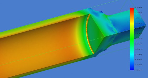
Quarter_L2_0p5mm_radius_75MPaPressure_corner_exceeds_uts_insideoftube_exceeds_yield.jpg
And a 3.3mm inside corner @ 75 MPa, because I can't help it.
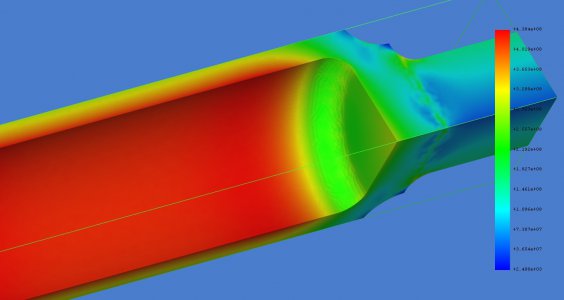
Quarter_L2_3p3mm_radius_75MPaPressure_corner_good_probablyexceeds_yield.jpg
Tube is either at, or just about to yield. Inside of tube yielded, outside is near yield threshold. Not something I'd be interested in placing near my neck or head.

So I guess the answer to my original question, is yes. It seems I can do some of this now.
 
Not disagreeing at all. We are in agreement! I merely did an analysis on an existing commercially produced (high end) product that has shipped product world wide. Not my design, nor do I endorse the design. Totally agree about the forces on the threads. The explosion pictures peaked my interest in learning about High Pressure Air and FEA. HPA is pretty dangerous, since the design has to be robust and can handle shock, vibration, impact and corrosion, all of which happen in the real world.
Sorry man didn't intend to sound like I was on you about it.

You know, the scarry thing about this is DOT cylinder are required to under go critical inspection and testing every 5 years for all the reasons you outline.

Most folks do not understand why these are so dangerous. An example I give when I talk to folks is helium, if you have 1 actual cubic foot of space and you put helium into the volume at 3000 psi there will be 380+ standard cubic feet of gas in that volume. The same example of air would be around 150, not exact but you get the idea.
No worries. This stuff has it's hazards. I may not know all of them, but I do know a few of them, and they have gotten my attention.

There's a darn good reason gas cylinders have to be inspected and tested. They carry a lot of energy. Big leaks can displace air and suffocate you. The gas can be poisonous, or flammable, or enhance burning, or, the list goes on...

My favorite weird gas is hydrogen. Compressed hydrogen (and helium) heat when expanding (at temperatures above a "magic" temperature). This is unlike most gases, which cool when expanding. So leaking hydrogen from high pressure cylinders in terrestrial temperatures self ignite from the heat generated from the leak. Hydrogen flames are mostly pale blue-violet and UV, so they are hard to see, especially in daylight. One of the additional hazards of storing compressed hydrogen.
 
It has been brought to my attention, that the analysis of something like this tube needs to be non-linear, rather than a simple static linear sim. So, I finally figured out a way to do this. I grabbed the non-linear data from https://icme.hpc.msstate.edu/mediaw...4-T3_Stress-Strain_and_Fatigue_Life_Data.html . Put in the non-linear breakpoints, for "MaterialMechanicalNonlinear", (only the first two of them, had a feeling this might be a long sim) and let it run. Simulator had a lot of convergence issues, but chugged along. A half hour later, on a quarter model, the sim generated over 400MB of data sets, and also a bunch of messages, that I don't know what they mean yet. So I was able to graph the equivalent plastic strain of the tube. "I've been told" that one is looking for strains > 3% over some area (volume?) to determine if there is a problem. Not sure what exactly that means, this is getting over my head. If anyone can explain this in a simpler fashion, it would be helpful.

The more I learn, the more confused I get... There's a lot to this!
2024T3 1/4 tube pressurized to 2.5x nominal pressure (nom = 300 bar), 0.4mm inside corner. Peak equivalent plastic strain of just under 1%, in the middle of the high pressure area.
non_linear_equiv_plastic_strain.png
 
Hats off to you for working through all the issues with getting answers out of FreeCad FEM.
 
Hats off to you for working through all the issues with getting answers out of FreeCad FEM.
Thanks. Just being stubborn, (ok driven,) getting through this. Sometimes, that's what you have to do. I have serious gaps of knowledge about this stuff - a lot of it I just don't grasp yet. Just because one can put stuff in the computer, doesn't mean one fully understands the results... I have a huge non-understanding of how one would determine the probability of fracture or catastrophic rupture. What I have learned so far is I wouldn't use this material for the tube.
 
Thanks. Just being stubborn, (ok driven,) getting through this. Sometimes, that's what you have to do. I have serious gaps of knowledge about this stuff - a lot of it I just don't grasp yet. Just because one can put stuff in the computer, doesn't mean one fully understands the results... I have a huge non-understanding of how one would determine the probability of fracture or catastrophic rupture. What I have learned so far is I wouldn't use this material for the tube.
Actually, the best material would be a seamless stainless tube with actual stainless cap and connectors welded with an orbital welder. The weight of the vessel I just described would not be any greater. Nice work on your learning project.

Everyone thinks, that with computers, all you have to do is enter the data and the computer will spit out the answer. Well it isn't that easy, you have to have an idea of what you are looking at otherwise you may get trash....
 
Found out that the nonlinear materials graph I used isn't complete. It doesn't go to breakage, usually symbolized by an x on the graph. These graphs are a bit confusing at times, and you really need to understand a lot to use them appropriately. Furthermore, there's longitudinal and lateral modes, not to mention material thickness and whether the stock was extruded or not. A lot of stuff to absorb. Have to admit, this would have been a lot easier, had I taken some ME courses, but I took a different path in life.

Hmm, maybe I'll have one more go at this. Curious if adding the additional information will remarkably change the results. The risk for me is making a wrong choice of the graph to use.

I already know that a cylinder like this did rupture and where it let go. There was a fracture that ran lengthwise in the high pressure region and a total separation of the inside corner area from the tube. So the unthreaded end blew off. Must have been pretty exciting. Wouldn't surprise me if it had been dropped, because I don't see how someone could have survived had it ruptured near the person's neck. Either that or they were darn lucky.
 
Thanks. Just being stubborn, (ok driven,) getting through this. Sometimes, that's what you have to do. I have serious gaps of knowledge about this stuff - a lot of it I just don't grasp yet. Just because one can put stuff in the computer, doesn't mean one fully understands the results... I have a huge non-understanding of how one would determine the probability of fracture or catastrophic rupture. What I have learned so far is I wouldn't use this material for the tube.
No doubt about the computer issues, the results are only as good as the model and data, not to mention interpretation. While using FreeCad FEM would be dubious for any critical design, as a post-mortem learning tool it is interesting. Adding to the challenges translating this to an effective design, at least by my (poor) understanding, is that aluminum is more prone to fatigue issues.
Anyway, thanks for sharing this.
I don't think FreeCAD is inherently dubious for critical design, any more than a paid tool. At least the equations and whatnot are inspectable and open source.

The real issue is having the requisite background information and training to effectively use any of these tools. I'm just a tinkerer. If I were to create any pressure vessel, it would be hydro tested first! High pressure designs can be dangerous, and that's why there are so many inspections, regulations and rules world wide.

And yes, aluminum, has fatigue issues. 2024 seems like a sub optimal choice.
 
Back
Top