Anyone know how to use the FEM analysis tools in FreeCAD?

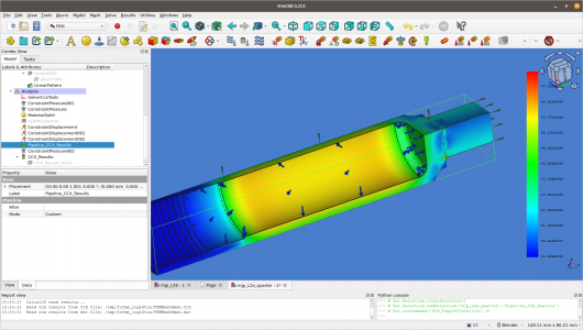
Took out the threads to simplify the model. Finally got it to mesh although there were two warnings. When FreeCAD created the mesh object it put it in the wrong place... Why that is, I do not know... Put it in the correct place in the heirarchy, and meshing was able to complete. Unfortunately, the analyzer has quit due to a non positive jacobian fault. Still, it is some progress...
View attachment 446301
Have to say, this is quirky as all get out - a work in progress.
If all you are attempting to do is find the burst pressure that can be accomplished with Barlow's Formula.
 
If all you are attempting to do is find the burst pressure that can be accomplished with Barlow's Formula.
Actually, I am attempting to do postmortem analysis of a burst tube. Fortunately, not mine. The design seems to have some issues, and I'm doing some sleuthing to figure out where the peak stresses were, and how to mitigate them. I have no skin in the game, save for the desire to further understand the issue. Been a lot of blather about the causes, and thought an FEA might be appropriate. So taught myself some of the basics and here I am. Apparently this design has pushed some limits, a wee bit. But the root cause for the burst isn't known yet. Anyways, it is capturing my fancy, and I'm learning about stuff. Barlow's formula is strictly for the pipe, but does not take into account the ends or things like that. Much of the fun is in the details...

This quarter tube is pressurized to 3.5X nominal, which this material cannot take. The original is not constructed with a beautiful inside corner like this one. The original had maybe a < 0.4mm radius, which is very bad. You can also see the stress risers on the junction of the block to the right with the pressure tube. The tiny red spots which are way above ultimate tensile strength of 2024T6. I've learned a lot playing around with this. For now, I am going to attempt to determine the safety factor of the portion that is of interest. In the burst tube it looks like the location of the peak stresses were nearly exactly where the tube fractured. I am far from an expert, but it has been interesting learning a little about this stuff.
1683835228971.png
von Mises stress of 2024T6 tube pressurized to 105 MPa. Yield strength of material ~ 305-340 MPa depending on how optimistic one is.
 
Engineers seem to think that they can simplify any system by analyzing based on frictionless spheres. This is a case of that, where wild assumptions plus computers equal something useful.

I use FEA tools in SolidWorks to spot check and answer what-ifs, but what I don't like about calculators like these is the simple fact that if you feed it numbers, it gives numbers as a result. It does take education and experience (and common sense) to interpret the result and determine if it is useful, or even correct. I can fist-mash my adding machine until it prints out a result, but I won't write that result on a check and drop it in the mail just because it came up on my calculator.

I'm not familiar enough with freecad to help with the setup, but I'd eliminate features like threads form the drawing until the time comes where you need to analyze the threads. The closer that tube looks to a boring frictionless sphere, the more accurate your FEA will be.
Can't disagree with garbage in = garbage out. The pseudo-threads (they are not even real threads) are more for the reader to visualize the part. In real life the threads are not in a pressure zone.

The threads are however subject to stress, because there's 30 bar of pressure ordinarily pushing a plug outwards. I'm not modeling that at the moment, mostly because I haven't figured out how to do it. The plug didn't break. The tube exploded, with a crack starting in the inside corner of the pressure vessel. The original burst tube seemed to have had an inside corner radius of 0.2mm, at least it looked like it from the pictures. In the picture above the radius is set to 3.3mm, and the stress riser vanishes.

Honestly, I'm just doing all this to learn more about high pressure air. Prior to a few weeks ago, I had never used mechanical FEA at all. I have used EMag FEA though, as well as FDTD. But yea, I'm just screwing around with this, getting a feel for stuff before I do anything serious. My first designs will be hydro-tested, because I value my neck, and all the rest of my body parts...
Please do not take this as me preaching or the proverbial "I need to be right" or any of that goo, This is me discussing something near and dear to my heart. and my social skills are sometimes lacking.

I didn't mean to step on your curiosity, you kinda have to understand that I saw what you are doing and assumed you were trying to work out something on a project and thought I could help. A bit of History because you never know who you are talking to on the internet, I am actually a Sr. Piping Designer, I have designed Piping systems for process units Oil and Gas, Offshore drilling rigs, Ground support for Aerospace companies developing launch vehicles, Storage systems compression equipment and air separation for the Industrial gas industry (gas up to 15000 PSI and Cryogenics) etc.... so when I see a puzzle shaped like a pipe I cannot help myself :).

In the case of your puzzle, based upon what you told me, There are several likely reasons for the failure. First and number one is it a seamless tube? if not, it very likely failed at the seam, particularly if it was an extrusion with a dividing seam. Next, you are absolutely correct in your statement about the corners and if the bottom was flat in addition then the pressure in the middle of that flat would have applied enough distortion through its leverage at the corners to cause the tube to have uneven pressure along its long axis which would cause it to fail. a round cylinder is only good for high pressure as long as the hoop stress is even circumferential to the long axis, introducing an uneven stress will always lead to failure.

Just as a note, the threads are a great point for failure as well, threads introduce stress risers.

as far as Barlow's, it doesn't care what you call the cylinder nor How long it is, it works specifically based upon diameter, wall thickness and yield and it will tell you what the actual burst pressure is to within +/-5%. The one thing Barlow's doesn't factor in is poor manufacturing.

I hope there is something of interest there for you.

Pontiac428, I have Solidwork with Cosmos and you are correct, its good stuff and I am not very familiar with FreeCAD either.
No offense taken. I know that I don't know a lot about this. A couple of things that are known. The tube in question was machined from solid extruded appropriately tempered stock. No welds, no seams. The bottom of the pressure vessel was flat. It was apparently bored out with a tool called a U drill. From what I understand, the maximum radius for the inserts for the drill is about 1mm. From the pictures of a cross sectioned similar piece the radius was probably under 0.4mm. It looked like a sharp edge, not radiused. A stress crack developed in the sharp corner, that's from recovered debris.

It's murky the situation that was prior to the explosion. Could have been user error, maybe the pressure vessel was dropped, or something else like corrosion further opening up stress cracks. True reason is currently unknown. These cylinders are being used in PCP airguns. That cylinder would be close to one's neck, which would ruin your day if it exploded.

The threads are isolated from pressure by an o-ring. But obviously the plug has the force of the high pressure air pushing on it. Sometime, I will look at that. The ID is just shy of 30mm, with 300 bar on it, that the threads have to resist. It's amazing that this stuff seems to work.

So far, out of an alleged production of far more than 10K PCP airguns of this design, there's been one explosion. It's one too many. This design appears to have little margin. And to make it more fun, there doesn't seem to be any world wide standards on these small volume cylinders, including in the US, to my knowledge. Not everyone seems to be using the same safety factor to yield, if they even use that.

For me, it's the opportunity to learn more mechanical design things and maybe the change to make a toy of my own. But seriously, anything like the above, I'd have hydro tested before I'd ever use it with compressed air. Seen way too many pictures of exploded tanks...
 
I think your class of pressure vessel falls through the regulatory cracks because individuals are buying, using, and transporting them as private citizens. Without a DOT-E exemption or a DOT permit, it would be illegal for anyone to move one of those cylinders on a roadway... but only if they were being paid to do so, because those are commercial regulations! That gets you out of expensive permitting and testing and design review by the authorities. It also means big trouble if anything goes wrong. It takes cojones to sell a bottle that holds 300 bar pressure. It takes bigger ones to charge a cylinder without a DOT number on it to that pressure and hold it against valuable parts. I liked this story a lot better when it was just an anonymous tube that failed and burst.
 
No offense taken. I know that I don't know a lot about this. A couple of things that are known. The tube in question was machined from solid extruded appropriately tempered stock. No welds, no seams. The bottom of the pressure vessel was flat. It was apparently bored out with a tool called a U drill. From what I understand, the maximum radius for the inserts for the drill is about 1mm. From the pictures of a cross sectioned similar piece the radius was probably under 0.4mm. It looked like a sharp edge, not radiused. A stress crack developed in the sharp corner, that's from recovered debris.

It's murky the situation that was prior to the explosion. Could have been user error, maybe the pressure vessel was dropped, or something else like corrosion further opening up stress cracks. True reason is currently unknown. These cylinders are being used in PCP airguns. That cylinder would be close to one's neck, which would ruin your day if it exploded.

The threads are isolated from pressure by an o-ring. But obviously the plug has the force of the high pressure air pushing on it. Sometime, I will look at that. The ID is just shy of 30mm, with 300 bar on it, that the threads have to resist. It's amazing that this stuff seems to work.

So far, out of an alleged production of far more than 10K PCP airguns of this design, there's been one explosion. It's one too many. This design appears to have little margin. And to make it more fun, there doesn't seem to be any world wide standards on these small volume cylinders, including in the US, to my knowledge. Not everyone seems to be using the same safety factor to yield, if they even use that.

For me, it's the opportunity to learn more mechanical design things and maybe the change to make a toy of my own. But seriously, anything like the above, I'd have hydro tested before I'd ever use it with compressed air. Seen way too many pictures of exploded tanks...
I agree with Pontiac428 this information makes a great deal of difference. When we fabricate a part which is for use at those high pressures we test to 1.5x the operating pressure and we usually do not make it out of 2000 series aluminum. A square end and the threads are both poor for a pressure vessel this size. The threads do not have to have pressure on them, they are stress risers the diameter of the vessel with 4350 pound of force per square inch pulling on them. ((Area of the major diameter - the area of the minor diameter) x depth of threads) x 4350 = total force applied.
 
I agree with Pontiac428 this information makes a great deal of difference. When we fabricate a part which is for use at those high pressures we test to 1.5x the operating pressure and we usually do not make it out of 2000 series aluminum. A square end and the threads are both poor for a pressure vessel this size. The threads do not have to have pressure on them, they are stress risers the diameter of the vessel with 4350 pound of force per square inch pulling on them. ((Area of the major diameter - the area of the minor diameter) x depth of threads) x 4350 = total force applied.
Not disagreeing at all. We are in agreement! I merely did an analysis on an existing commercially produced (high end) product that has shipped product world wide. Not my design, nor do I endorse the design. Totally agree about the forces on the threads. The explosion pictures peaked my interest in learning about High Pressure Air and FEA. HPA is pretty dangerous, since the design has to be robust and can handle shock, vibration, impact and corrosion, all of which happen in the real world.
 
I think your class of pressure vessel falls through the regulatory cracks because individuals are buying, using, and transporting them as private citizens. Without a DOT-E exemption or a DOT permit, it would be illegal for anyone to move one of those cylinders on a roadway... but only if they were being paid to do so, because those are commercial regulations! That gets you out of expensive permitting and testing and design review by the authorities. It also means big trouble if anything goes wrong. It takes cojones to sell a bottle that holds 300 bar pressure. It takes bigger ones to charge a cylinder without a DOT number on it to that pressure and hold it against valuable parts. I liked this story a lot better when it was just an anonymous tube that failed and burst.
These are many of these pressure vessels (not this design) being sold to the PCP community. Most are similar or identical to air cylinders and even come with certifications, at least CE. Some even with DOT. AG manufacturers have been selling these for more than a decade. The exploded part was obviously a custom design to make a compact airgun. If I were to even consider something like this, I wouldn't be using 2024, nor would it have sharp inside corners. Learning FEA was quite instructive.

Way too many things contributed to the explosion. Sharp edges causing stress risers in excess of yield, wrong material, wet air leading to internal corrosion, incomplete anodization to minimize corrosion, constant pressure cycling, and maybe shock due to a drop. Nearly everything that could go wrong did. Certainly not apologizing for the manufacturer, but for this unit, nothing went well.
 
Back
Top