ARC-170's Craftsman 101.07403 lathe restoration thread

Here's the latest:

39. SIDE GUARD
I drilled out the holes in the mounting plate and moved the motor over. The axle on the motor sticks out too far, but I got it so it just clears the cover. When the machine rattles, it sometimes moves the cover.

40. BELT COVER TAB
Still don't know what this does. Seems like it should act as a stop for the cover.

41 BELT COVER DOOR ALIGNMENT
I decided this wasn't worth the trouble. It aligns enough to work.

42. MOUNTING THE LATHE
I placed the oil drip pan under the lathe, bolted it to the MDF/22Ga steel table. I used an "L" channel under the headstock to bear the weight and add some stiffness. I've mad a few cuts and it seems sturdy enough.

43-44. CHUCKS
I reassembled one. The other one is proving difficult to get apart. Stay tuned.

45. LEVELING THE LATHE
I've decided I'm going to put the machine on the garage floor.
a. Should I bolt it to the floor?
b. I have my grandfather's machinist's level. I will use this to level the machine, Anything I should know?

Once I do this, I'll then align the head and tail stocks.

46. HEADSTOCK ALIGNMENT
What's the best way to accomplish this? The barbell method seems the best, but I'd like to use the 3-jaw chuck, since that's the one I'll use the most. Thoughts?

47. TAILSTOCK ALIGNMENT
I thought I would chuck up a piece of long-ish round stock between centers and make a cut. If it's tapered, I adjust the tailstock until there's no taper.
I also thought I might run out the tailstock as far as it will go and measure it with an indicator at both ends and see if they are the same.
Thoughts?
 
47. TAILSTOCK ALIGNMENT (con't)
I found this in another post:

A test bar only needs a ring on each end that's the same diameter and perfectly centered. Center drill both ends of a bar. Using a dead center in the tailstock, turn a clean area next to the tailstock. Flip the bar and do it again. Do a final pass on each end (flipping the bar and working at the dead center) using a shear tool (for good finish on steel), and without moving the crossfeed. You should have identical diameters on both ends, perfectly centered because it was running on a dead center.

a. If I use a center drill on an out-of-alignment tailstock will that matter?
b. Why a dead center? Less chance of movement?
 
46-47. HEADSTOCK & TAILSTOCK ALIGNMENT (con't)
I found this in another post:

There is no need to turn a test bar or to have one perfectly centered. Rollie's Dad's method will work to adjust the tailstock center.

For those who are not familiar with Rollie's Dad's method, it only requires a rigid test bar uniform roundness and, preferably, diameter. If a bar is mounted in a lathe chuck and the surface near the headstock is swept with a DTI, the average of the minimum and maximum readings will be the spindle axis position plus the radius. Runout is automatically compensated for. If the carriage is then moved to the far end of the bar and the process repeated the average of the two readings will be the same if the carriage ways are parallel to the spindle axis. This process is used to align the lathe bed to the spindle.

For adjusting the tailstock, a slightly different approach is taken. the test bar is mounted between centers. A lathe dog and face plate are used to turn the bar. The minimum and maximum readings are averaged at each of two positions. If the tailstock is properly aligned the two averages will be the same. Any runout is canceled out in the process so the center drills do not have to concentric with the bar diameter. The tailstock can to be moved correct any difference without having to go back to check the headstock readings although it would be wise to do a final verification.

If the headstock center is known to be true (no runout), the bar can be rotated by hand, no dog and face plate required.
 
40. BELT COVER TAB

I had also assumed that it was a Stop. If there is nothing there for it to push against, then I don't know what else it could be for.

42. MOUNTING THE LATHE

First a terminology correction. When referring to material, regardless of whether it is steel, aluminum, whatever, Channel has three (or six) sides, generally at right angles to each other. If the material only has two (four) sides at right angles to each other, it is called Angle, as in steel angle, aluminum angle, etc. Sometimes, steel angle is described as "angle iron" in older texts.

45. LEVELING THE LATHE

a. Yes.
b. Level the bench, stand, cabinet, etc. to the accuracy of a carpenter's level. If you have an oil pan with raised sides and a drain hole in one corner, tilt the bottom of the pan slightly toward the drain hole. Typically, the drain will be at the right end but may be in the front or rear corner. Then level the lathe bed both fore and aft and left and right to the accuracy of the machinists level. Before starting, ensure that your level is accurate by laying it on the bed left to right, noting the exact position of the bubble, then rotating it 180 degrees and noting the position. The two positions should be the same.

47. TAILSTOCK ALIGNMENT (con't)

A test bar that you are going to keep for future use should be at least 1" in diameter and around 12" long. Before making it, mount a dead center in the spindle and the tailstock ram. Retract the ram to zero and lock it. Slide the tailstock toward the headstock until the centers nearly touch and adjust the tailstock back-set to as near zero as you can eyeball it.

Remove the centers, install a three jaw chuck on the spindle, and mount the test bar in the chuck. Set up your steady rest near the chuck and then slide it down near the tailstock and lock it in place to keep the test bar from bending away from the cutter. Install a drill chuck in the ram and mount a good center drill. Center drill the end of the bar. Flip the bar end for end and repeat. Remove the steady rest, reinstall both dead centers and at the spindle install a face plate. Mount the bar between centers, with a lathe dog at the headstock end to drive the bar. Turn down the bar except for about an inch at each end to a diameter of around 1/4" less than the ends. Then turn down the tail stock end to clean up, leaving it larger than the bulk of the bar. Without touching the cross feed or compound settings, flip the bar end for end and repeat. You now have your test bar. Mount a dial test indicator to bear against the ends of the bar and zero it at the headstock. Crank it down to the tailstock end and adjust the back set to zero the DTI. To prove up the bar, flip it end for end and check that the indicator is still zeroed at both ends.

a. It shouldn't but the tailstock will be very close to centered during this step.
b. Yes.
 
45. LEVELING THE LATHE/BOLTING TO THE FLOOR

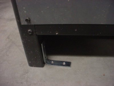
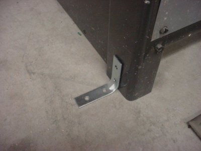
Here is what I'm thinking of doing for bolting it to the floor. Four 3 inch "L" brackets:
DSC00740.JPG

This is the same, but easier to do. However, it doesn't look as nice:
DSC00741.JPG

I thought I could add shims under the "L" brackets as needed. They need to go up about 1/16" or so in the front and on one side.

I'd use 2-3 inch-long 1/4" dia. lag bolts into lead anchors. My garage floor does not have any post-tensioned components.

The bench is about 22 Ga sheet metal. It's thinner than 16 Ga for sure. I need to add an "X" brace in the back to keep it laterally braced; it moves from side to side (right to left as you are standing at the lathe) too much. I'm not sure how much the "L" brackets will help correct this.
 
Last edited:
Here is what I'm thinking of doing for bolting it to the floor. Four 3 inch "L" brackets:
You might consider using sections of 3" angle iron instead of the L brackets. You could make them as wide as you want, so they would be easier to shim and would be stronger.
 
45. LEVELING THE LATHE/BOLTING TO THE FLOOR

The shims should go under the corner legs, not just under the angle brackets. Shimming under just the angle brackets alone would not be good. Do not use lag bolts longer that the lead anchors. Do not attach the angle brackets to the legs with sheet metal screws. Assuming that the legs are 2" x 2", use 1/4"-20 x 3" hex head bolts to attach the brackets to the legs, through holes drilled all of the way through the legs. I second using 3" steel angle cut off (again assuming the legs are 2" x 2") 1-1/2" long. The brackets shown in your photos are far too flimsy. Reinforce the side of the legs that are not against angle brackets with 1/4" x 1-1/2" steel flat bar cut 3" long. Install all of the angle brackets and backing bars flush to the floor before you start shimming. Your shims (assuming 2" x 2" legs and 3" angle brackets) should be 2-1/2" x 5-1/2".
 
45. BOLTING THE LATHE BENCH TO THE FLOOR
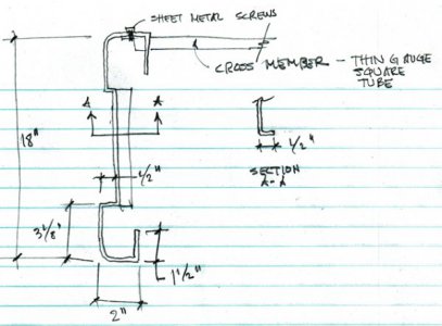
Here's what the plan view cross-section of the table looks like. It thought this might be helpful for the discussion:
bench anchoring sketch.jpg
The left and right sides of the table/bench are just formed 22 Ga (I think) sheet metal. There is no reinforcement such as tubing or anything folded over and welded together. The cross members hold everything together. I just got a bench with drawers and a cabinet on CL. I think it's rated to hold 1000 lbs. However it still needs to be stiffened for this application.

I went ahead and added the brackets at the ends (as shown in the second photo) and bolted them to the sides with 1/4"-20 bolts and nuts. They are anchored to the floor with #10 anchor bolts. BTW, they don't make lead anchors anymore, at least not in California. I used sleeve anchors. The side to side movement has been reduced, and the table is actually a bit more level than before.

I thought I would try this and see how it went. I thought heavy gauge angle iron was overkill since the sheet metal sides would be the weak point. Although, now that I think about it, the anchor bolts are probably the weak point. I suppose it depends on what forces are acting upon what components. I will take light cuts and see what happens.

I will definitely add any shims under the sides. Should they be under the brackets as well? That's how I read the above, just want to clarify.

47. TAILSTOCK ALIGNMENT
I aligned the tailstock and headstock by eye as close as possible.

I have some questions/clarifications about this:
Remove the centers, install a three jaw chuck on the spindle, and mount the test bar in the chuck. Set up your steady rest near the chuck and then slide it down near the tailstock and lock it in place to keep the test bar from bending away from the cutter. Install a drill chuck in the ram and mount a good center drill. Center drill the end of the bar. Flip the bar end for end and repeat. Remove the steady rest, reinstall both dead centers and at the spindle install a face plate. Mount the bar between centers, with a lathe dog at the headstock end to drive the bar. Turn down the bar except for about an inch at each end to a diameter of around 1/4" less than the ends. Then turn down the tail stock end to clean up, leaving it larger than the bulk of the bar. Without touching the cross feed or compound settings, flip the bar end for end and repeat. You now have your test bar. Mount a dial test indicator to bear against the ends of the bar and zero it at the headstock. Crank it down to the tailstock end and adjust the back set to zero the DTI. To prove up the bar, flip it end for end and check that the indicator is still zeroed at both ends.

c. I don't have a steady rest. Thought I'd use some 3/4" aluminum round stock since it fits in the spindle bore. I can center drill both ends without having it stick out too much. Thoughts?
d. "...install a faceplate." Why? I can't install 2 dead centers AND a faceplate. What am I missing?
e. I'm making a "barbell" shape, arent't I?
 
45. BOLTING THE LATHE BENCH TO THE FLOOR

>>
I will definitely add any shims under the sides. Should they be under the brackets as well? That's how I read the above, just want to clarify.

Yes. As Bill implied, when you tighten down the anchor bolts, you will bend the light gauge legs and maybe the brackets.

47. TAILSTOCK ALIGNMENT

c. Probably the three most useful and used accessories for an engine lathe are QCTP, Steady Rest and Live Center. You should have at least those three. While it is true that a 3/4" diameter bar can be stuck into the spindle bore, the problem with using 3/4" round bar is that by the time that you cut the center 80+% of the length down and then do cleanup cuts on the ends, the center part will be down to around 1/2". With a length of about 12", you might be surprised at how flexible this actually is. If you do not have a steady rest, you would be better served to up the diameter to 1-1/4" or 1-1/2" and run rather slow spindle RPM to minimize whip.

d. Actually, I should have said "dog driver plate", which is usually smaller than a face plate. But some at least face plates can double as driver plates. But whichever you use, I have never seen one of either that you can't also insert and use a dead center with. All of the Atlas lathes originally came with two 2MT dead centers (1MT with the 6") and a 3MT x 2MT adapter sleeve (2MT x 1MT with the 6"). The adapter plus center install in the spindle bore and the plate screws onto the threads. The center will stick out past the surface of the plate.

e. Yes. The main reason for turning down most of the length is so that the dial indicator doesn't drag on the bar as you traverse the distance between the right and left ends of the bar.
 
Last edited:
Back
Top