[Source] Bridge rectifier?

For a perfect diode the current vs. voltage curve is an exponential relationship so there is a _small_ increase across the diode as the current increases. But for real-world diodes the voltage drop across it is the internal resistance times the current plus the "perfect" diode voltage at that current. By "internal resistance" I mean the resistance due to the package elements plus the resistance of the (highly doped) silicon current path on either side of the diode. Natch, high-current diodes have a VERY low internal resistance....but it is always there.

At the risk of getting too deep into the mud, the silicon junction of high voltage diodes have to be lightly doped so when they're reverse-biased the depletion region is wide enough to prevent breakdown. This is exactly what you DON"T want for a high-current diode, because lightly-doped silicon has higher resistance. So the folks that make these devices have to employ all sorts of things to optimize their performance. The easiest approach: make them bigger, basically putting lots of smaller diodes in parallel. Eh, too much mud :D
 
Typically the P/N junction for silicon is 0.6 volts.

Maybe a bit more, or a bit less but for general troubleshooting just use 0.6.

Silicon transistors which are 2 P/N junctions are current devices, the voltage stays at the 0.6 but increases in current on the Base to Emitter increases Emitter to Collector.

This is just a diode, single junction so simple.

However, this is full wave bridge which basically folds the sine wave in 1/2 and flips it over.

120 VAC is RMS voltage, peak to peak is higher so voltage will be higher depending on load.

This is simple conversion for a DC Motor so simple.

Give the terminals a squish with pliers to close the contact area so they fit tight as loose ones create heat.

Sent from my SM-G781V using Tapatalk
 
All the electronic nerds come out of the woodwork (or metalwork) LOL
Check the polarity of your original rectifier- I think I see a red dot at the bottom in your picture- the fat black wire terminal
That could be the plus terminal, or not. You can't always go by the wire colors.
Usually bridges are marked +, -, and two "ac" or squiggle ~ terminals
 
Last edited:
All the electronic nerds come out of the woodwork (or metalwork) LOL
Check the polarity of your original rectifier- I think I see a red dot at the bottom in your picture- the fat black wire terminal
That could be the plus terminal, or not. You can't always go by the wire colors.
Usually bridges are marked +, -, and two "ac" or squiggle ~ terminals
Hehe, guilty as charged.

I find it interesting that different folks claim different voltage drops. It all depends on the diode technology. Look up Schottky diodes for an example.

And the collector-emitter voltage drop for a saturated bipolar transistor can be less than 100 millivolts. A MOS device can be lower yet. A lot of switching regulator IC's use MOS transistors, either internal or external, to commutate the current in an inductor, rather than a diode, to gain further efficiency compared to an ordinary diode. More mud.....sorry.... (well, not really :).
I've seen some textbooks use 0.6 v and some use 0.7 v for PN forward bias voltage drop. I think textbooks need to do a better job of clarifying the differences of back of the envelope calculation using various approximations vs real world characteristics. On the other hand one can find the truth from a well written datasheet. I've used a few rectifier bridges in series to lower the voltage of a linear PS in a pinch because it was a little too close to the max input voltage of some stepper drives. Bridges were mounted on a nice chunk of aluminum with some heat sink compound of course. With a varying amounts of current, the drop was consistent enough. Can't do that with a resistor. The only other PS I had too low of an output voltage. Still working without issue 12 years later. Yes, Schottky diodes are your friend in relatively low voltage and current situations when input voltage isn't a high as you like. Of course their switching characteristics is their raison d'etre.
 
All the electronic nerds come out of the woodwork (or metalwork) LOL
Check the polarity of your original rectifier- I think I see a red dot at the bottom in your picture- the fat black wire terminal
That could be the plus terminal, or not. You can't always go by the wire colors.
Usually bridges are marked +, -, and two "ac" or squiggle ~ terminals
Myself a first class "nerd", although I prefer the term "geek". It really doesn't matter, we are all attempting to assist and I seem to have started the digression. My attempt was not intended to be a class on diodes. Rather a few pointers to assist the OP with replacing with a "nonstandard" part. My nature is to (over)lecture and I may have overdone by a little. For this I apologize. But key to the subject is to orient the replacement part correctly. Not doing so can let the magic smoke out of the new part. And possibly other devices I'm not aware of. Where the OP acquires the replacement part is not my concern. It is a very common part and costly only in shipping. My intent was to stress this point and reassure a "non-geek" about ratings.

.
 
Just to follow up on my situation. New bridge came in. Replaced the old one luckily there was just enough room in box for it to fit. Plug the unit in and nothing. Wtf! Do a voltage check and nothing coming in.
Her initial problem was there was a break in the cord right by the junction box. I had found that one and found the neutral was separated in the insulation. I cut like 12” off and had wired up. Well where the wires come out of the molded plug I found the hot was separated and being held close enough to work from the molding on the plug holding it so the cord didn’t bend or flex. I had a new plug on hand wired it in and the machine works.
I wanna say thanks for the direction on the bridge rectifiers everyone thank you.
 
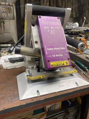
Well she binds carpet. Some carpets have a heavy ounce/weight super plush. When you try to bind the edge you need to bevel cut some of that nap back. Normal frizz yarn type carpet No you get into heavy once and wools you need too.
Some people have designs in a area rug and it’s all bevel cut or relieved to make it pop more.
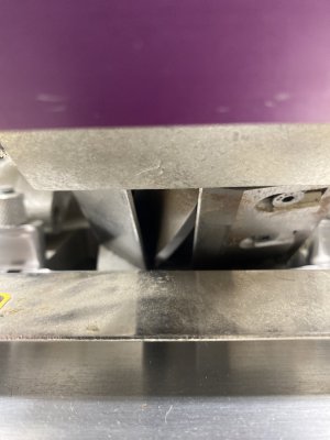
I still have the machine here so I took a pic. This machine bevels perimeter cuts. There’s another handheld one that does designs like I said above. Machine has a 5 bladed cutter spinning fast against another blade called a bedknife Super sharpimage.jpgimage.jpg
 
Was another wire on your bridge? Most bridges have four terminals, but I suppose that the case could be used as the "-" terminal. How was the original attached to the substrate?
read what he wrote, it broke off.. you can see the spot where it was right up front there.
 
Back
Top